Weld simulation method and device

An automatic welding and connection technology, which is applied in special data processing applications, instruments, electrical digital data processing, etc., can solve problems such as inaccurate simulation results, high manual labor intensity, and affecting speed

Active Publication Date: 2015-11-18
XIAMEN UNIV OF TECH +1
View PDF3 Cites 12 Cited by
  • Summary
  • Abstract
  • Description
  • Claims
  • Application Information

AI Technical Summary

Problems solved by technology

[0003] In the finite element analysis and modeling of passenger cars, the welding simulation is to connect the nodes at the connection ends of the two components one-to-one with rigid elements, while there are many welds in the traditional full load-bearing body frame, for example, a 12m-long There are about 30,000 to 50,000 rigid units that need to be established for the vehicle skeleton. To establish each rigid unit, the CAE engineer needs to operate the mouse twice, find the nodes that need to be connected through manual observation, and connect them one by one by manual clicking. If it is connected by one person, it will take two days to build rigid elements, which greatly affects the speed of finite element modeling, and manual operations are prone to omissions. In the later stage, all welds still need to be checked one by one. Conduct investigations to avoid missing connections, resulting in inaccurate simulation results, which greatly increases the workload of CAE engineers
[0004] Therefore, the current welding simulation method has the problems of low efficiency and high labor intensity.

Method used


Image

  • Weld simulation method and device
  • Weld simulation method and device
  • Weld simulation method and device

Examples


Embodiment Construction

[0026] Embodiments of the present invention provide a welding simulation method and device, which are used to improve the working efficiency of welding simulation, reduce frequent manual operations, and avoid errors caused by negligent manual operations.

[0027] In order to make the purpose, features and advantages of the present invention more obvious and understandable, the technical solutions in the embodiments of the present invention will be clearly and completely described below in conjunction with the accompanying drawings in the embodiments of the present invention. Obviously, the following The described embodiments are only some, not all, embodiments of the present invention. All other embodiments obtained by those skilled in the art based on the embodiments of the present invention belong to the protection scope of the present invention.

[0028] The terms "comprising" and "having" in the description and claims of the present invention and the above drawings, as wel...


PUM


Abstract

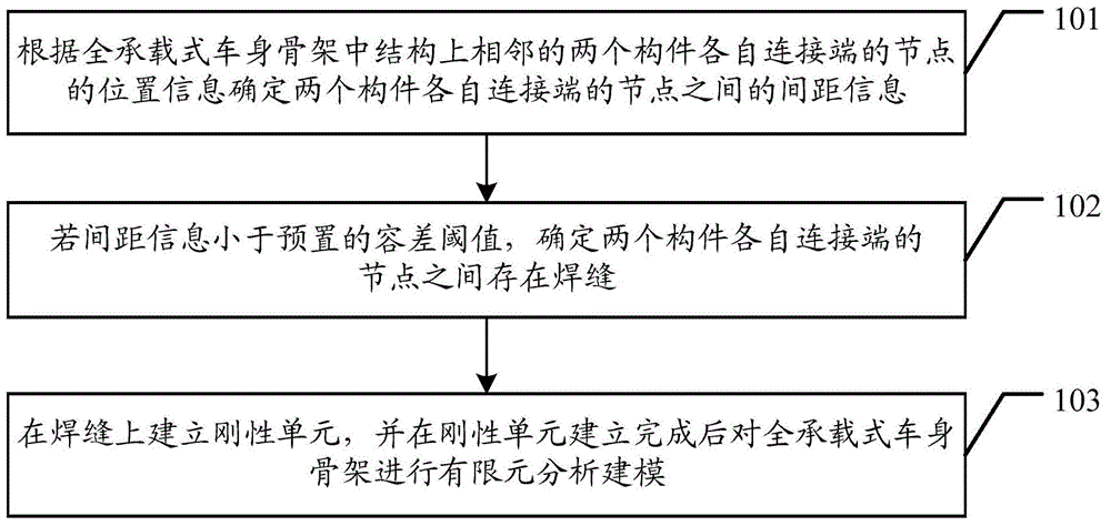
The present invention discloses a weld simulation method and device, which is used to improve the work efficiency of weld simulation, reduce manual frequent operation, and avoid the error caused by negligence of manual operation. The weld simulation method provided by the present invention includes: according to location information of joints of each connection end of adjacent two members in a structure of a self supporting body frame, determining space information among joints of each connection end of the two members; if the space information is less than a preset tolerance threshold, determining that weld seams exist among joints of each connection end of the two members; establishing rigid elements on the weld seams, and carrying out a finite element molding on the self supporting body frame after the rigid elements are established.

Description

technical field [0001] The invention relates to the technical field of automobile manufacturing, in particular to a welding simulation method and device. Background technique [0002] The full load-carrying bus is one of the passenger cars with high safety at present. The full load-bearing structure makes the driving of the bus more agile, stable, comfortable and safe. In addition, its low-floor design, humanized configuration, and low The advantages of emission, environmental protection, and large passenger space have created the unique product advantages of full-carrying buses. Computer Aided Engineering (CAE, Computer Aided Engineering) technology has been widely used in the field of full-load passenger car manufacturing, especially in various processes of passenger car R&D. The most important is the fully load-bearing body frame, which is welded by a series of rectangular steel or square steel. The structural strength analysis of the bus frame is often completed by CAE....

Claims


Application Information

Patent Timeline
IPC IPC(8): G06F17/50
Inventor 彭倩卢光华韩锋钢
Owner XIAMEN UNIV OF TECH
Why Eureka
Try Eureka