Head-mounted display device and its optical lens system
An optical lens and lens technology, applied in optics, optical components, instruments, etc., can solve the problems of small working distance from eyepiece to display screen and cannot meet the needs of use, and achieve the effect of excellent imaging quality and guaranteed field of view.
- Summary
- Abstract
- Description
- Claims
- Application Information
AI Technical Summary
Problems solved by technology
Method used
Image
Examples
Embodiment 1
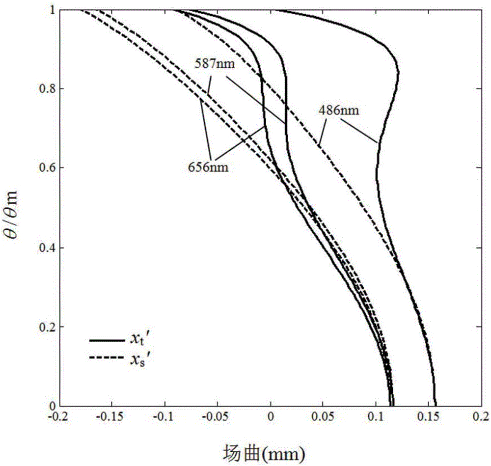
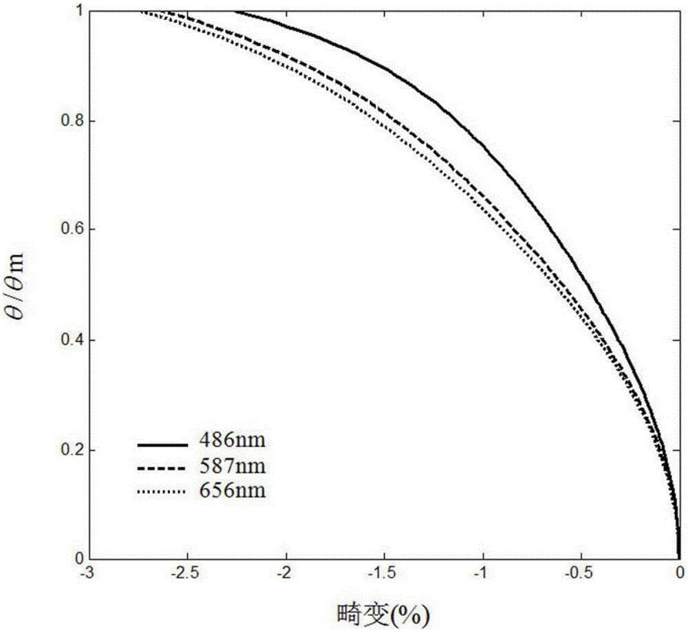
[0072] refer to figure 1 As shown, the optical lens system of this embodiment includes sequentially along an optical axis I from the light exit side A1 to the light entrance side A2: an aperture stop AS1, a first lens L1, a second lens L2, A third lens L3, a fourth lens L4, a fifth lens L5, and a sixth lens L6. Each lens has a spherical lens with refractive power, and has a first surface facing the light-emitting side A1 and allowing the light to pass through, and a second surface facing the light-incident side A2 and allowing the light to pass through.
[0073] The first lens L1, the second lens L2, the third lens L3, the fourth lens L4, the fifth lens L5 and the sixth lens L6 of the optical lens system of this embodiment are exemplarily made of glass or plastic materials, And the detailed structure is formed as follows:
[0074] The aperture (aperture stop) AS1 is an equivalent aperture, and the entity of this component may not be provided in practical applications. The ap...
Embodiment 2
[0091] refer to Figure 5 As shown, the optical lens system of this embodiment includes sequentially along an optical axis I from the light exit side A1 to the light entrance side A2: an aperture stop AS1, a first lens L1, a second lens L2, A third lens L3, a fourth lens L4, a fifth lens L5, and a sixth lens L6. Each lens has a spherical lens with refractive power, and has a first surface facing the light-emitting side A1 and allowing the light to pass through, and a second surface facing the light-incident side A2 and allowing the light to pass through. In order to make the drawings more concise, only the numbers on the surfaces different from those in Embodiment 1 are marked in the drawings of this embodiment, which is the case for the following embodiments, and will not be repeated here.
[0092] The surface design of each lens in this embodiment is basically the same as that in Embodiment 1, except that the second surface S12 of the first lens L1 in this embodiment is a p...
Embodiment 3
[0100] refer to Figure 9 As shown, the optical lens system of this embodiment includes sequentially along an optical axis I from the light exit side A1 to the light entrance side A2: an aperture stop AS1, a first lens L1, a second lens L2, A third lens L3, a fourth lens L4, a fifth lens L5, and a sixth lens L6. Each lens has a spherical lens with refractive power, and has a first surface facing the light-emitting side A1 and allowing the light to pass through, and a second surface facing the light-incident side A2 and allowing the light to pass through.
[0101] The surface design of each lens in this embodiment is basically the same as that in Embodiment 1, except that the second surface S12 of the first lens L1 in this embodiment is convex, and the second surface S62 of the sixth lens L6 is flat. In addition, the radius of curvature of each lens of this embodiment and the thickness of the lens on the optical axis are slightly different from those of Embodiment 1. In this e...
PUM
 Abstract
Description
Claims
Application Information
 - R&D
- Intellectual Property
- Life Sciences
- Materials
- Tech Scout
- Unparalleled Data Quality
- Higher Quality Content
- 60% Fewer Hallucinations
Browse by: Latest US Patents, China's latest patents, Technical Efficacy Thesaurus, Application Domain, Technology Topic, Popular Technical Reports.
© 2025 PatSnap. All rights reserved.Legal|Privacy policy|Modern Slavery Act Transparency Statement|Sitemap|About US| Contact US: help@patsnap.com


