
Design method of horizontal flying probe test machine

A flying probe testing machine and design method technology, applied in the direction of electronic circuit testing, etc., can solve the problem of inconsistent precision between the driving end and the driven end of the unilateral drive testing machine, etc.

Active Publication Date: 2015-11-18
HANS CNC SCI & TECH
View PDF9 Cites 4 Cited by
  • Summary
  • Abstract
  • Description
  • Claims
  • Application Information

AI Technical Summary

Problems solved by technology

[0008] The purpose of the embodiment of the present invention is to provide a design method of a horizontal flying probe tester to solve the problem of inconsistency in accuracy between the driving end and the driven end of the existing unilateral drive tester

Method used


Image

  • Design method of horizontal flying probe test machine
  • Design method of horizontal flying probe test machine
  • Design method of horizontal flying probe test machine

Examples


Embodiment Construction

[0023] In order to make the object, technical solution and advantages of the present invention clearer, the present invention will be further described in detail below in conjunction with the accompanying drawings and embodiments. It should be understood that the specific embodiments described here are only used to explain the present invention, not to limit the present invention.

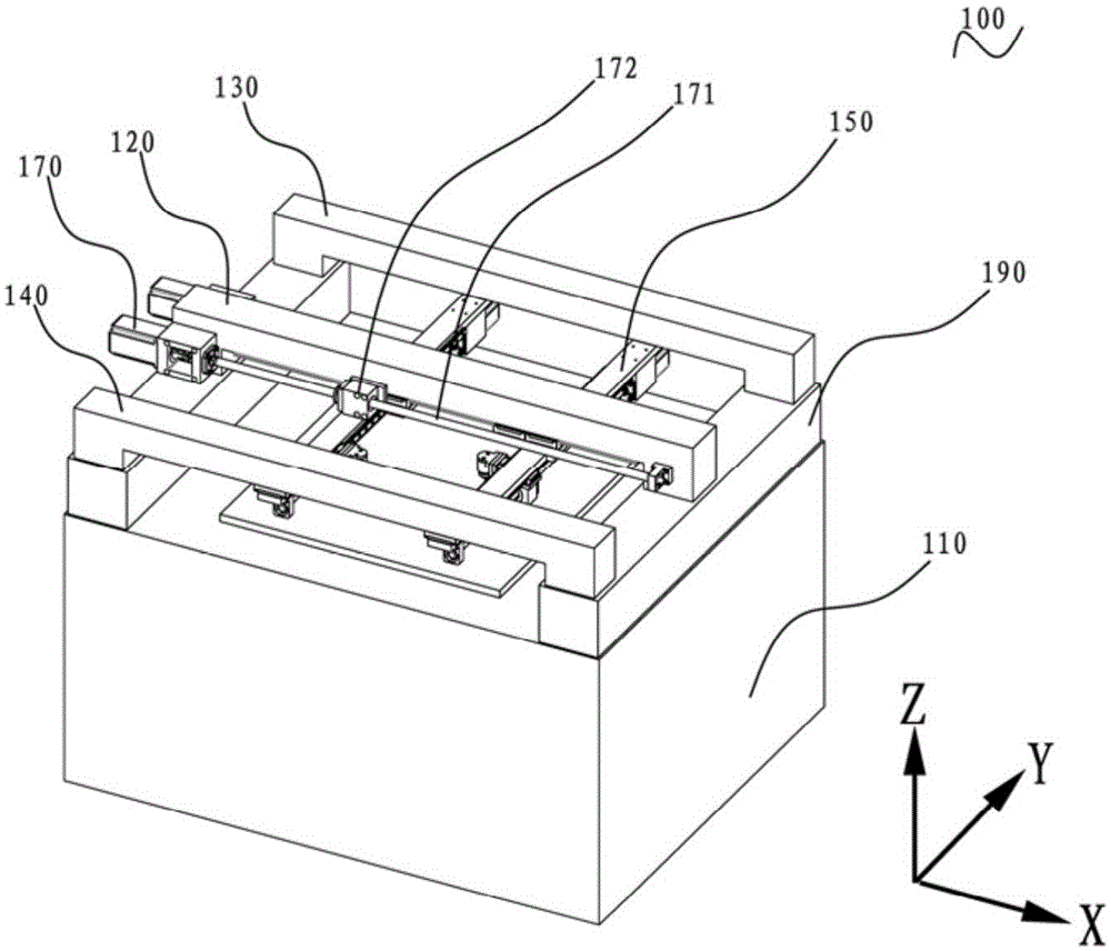
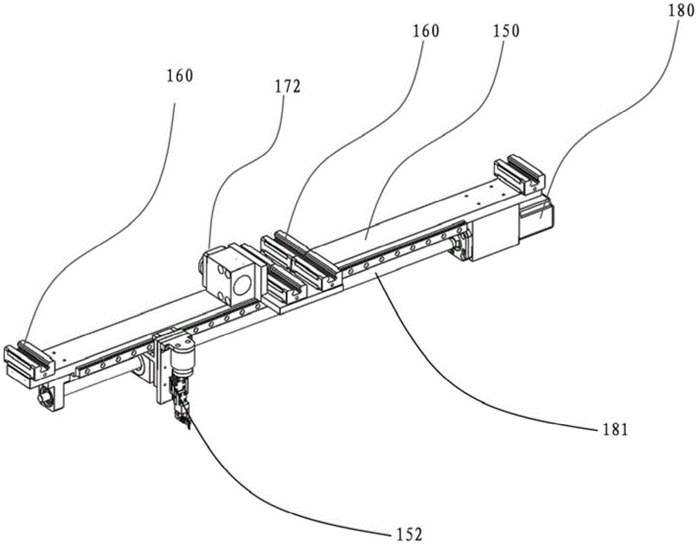
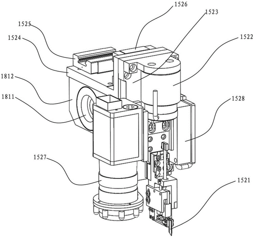
[0024] Such as figure 1 , 2 As shown, the embodiment of the present invention provides a design method of a horizontal flying probe testing machine 100, the horizontal flying probe testing machine 100 includes a bed 110, a movable beam 150 suspended above the bed 110 , and the test head 152 movable on the span beam 150, the test head 1152 can move up and down in the Z-axis direction to realize the test of the test board. Specifically, the design method includes setting the first crossbeam 120, the second crossbeam 130, and the third crossbeam 140 in the same direction above the bed 110; Below th...


PUM


Abstract

The invention is suitable for the field of flying probe test machine manufacturing, and provides a design method of a horizontal flying probe test machine. The horizontal flying probe test machine comprises a bed body, span beams which are arranged above the bed body, and test heads which are movably arranged on the span beams. The design method comprises the steps that a first cross beam, a second cross beam and a third cross beam are suspended above the bed body in the same direction; two span beams are suspended beneath first, second and third cross beams; two first drive devices which drive two span beams to move along the first cross beam are arranged on both sides of the end part of the first cross beam; the first cross beam is located in the middle of the bed body; and the second cross beam and the third cross beam are respectively located on both sides of the bed side. According to the invention, the first drive devices are arranged in the middle of the bed body to drive the middle position of the span beams; the horizontal flying probe test machine has the advantages of short overall span, large test range and high test precision; a single-drive mode is used to reduce the cost; and the precision consistency of the drive ends and the driven ends of the span beams is improved.

Description

technical field [0001] The invention belongs to the field of manufacturing a horizontal flying probe tester, in particular to a design method of a horizontal flying probe tester. Background technique [0002] The flying probe testing machine is a device that is driven by a motor to quickly move the probe to touch the pad or device pin of the test board and measure the electrical properties. The main effects of the flying probe testing machine are precise motion control, reliable electrical performance, Fast test efficiency, diverse test capabilities, and a good mechanical structure are the keys to achieve the above effects. With the development of high-density, multi-layer, and miniaturized PCB boards, the line width and line spacing of PCB boards continue to shrink, and the requirements for testing accuracy and testing efficiency of flying probe testing machines are also getting higher and higher. [0003] According to the structure, the flying probe testing machine can us...

Claims


Application Information

Patent Timeline
Patent Type & Authority Applications(China)
IPC IPC(8): G01R31/28
Inventor 陈百强李宁王星翟学涛高云峰
Owner HANS CNC SCI & TECH
Learn More