A piston testing device

A test device and piston technology, applied in the direction of internal combustion engine testing, etc., can solve the problems of long development cycle and unsuitable for large-scale testing, and achieve the effect of improving compliance

Active Publication Date: 2018-01-26
湖南江滨机器(集团)有限责任公司
View PDF7 Cites 0 Cited by
  • Summary
  • Abstract
  • Description
  • Claims
  • Application Information

AI Technical Summary

Problems solved by technology

[0003] In order to solve the problem that the actual durability test of the existing engine bench has a long development cycle and is not suitable for large-scale testing, the present invention provides a new piston testing device

Method used


Image

  • A piston testing device
  • A piston testing device

Examples


Embodiment Construction

[0018] In order to enable those skilled in the art to better understand the technical solutions of the present invention, the present invention will be further described in detail below in conjunction with the accompanying drawings and specific embodiments.

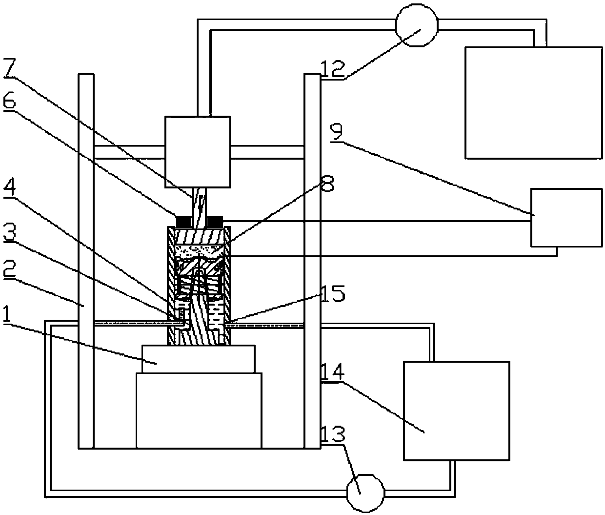
[0019] figure 1 It is a schematic diagram of Embodiment 1 of the piston testing device of the present invention. From figure 1 It can be seen that the piston testing device in this embodiment simulates the force situation of the piston in the top dead center area of ​​the cylinder, that is, the force situation of the piston in the cylinder when the cavity fuel mixture is in the deflagration state, and simulates the deflagration shock Action on the top of the piston. The piston testing device in this embodiment includes a platform base 1, a platform bracket 2, a piston connecting rod 3, a cylinder liner 4 and a thermomechanical coupling unit, wherein the platform base 1 and the platform bracket 2 respectively play a supp...


PUM


Abstract

The invention provides a piston testing device, which includes a platform base, a platform bracket, a piston connecting rod, a cylinder liner, a cooling unit and a thermomechanical coupling unit; the piston connecting rod and the cylinder liner are installed on the platform base; the The thermal-mechanical coupling unit is installed on the platform support to provide a periodic high-temperature and high-pressure environment for testing; the piston to be tested is connected to the piston connecting rod through a piston pin and installed in the cylinder liner; the thermal-mechanical coupling unit, The cylinder liner and the piston form a sealed space. The periodic pressure and continuous high temperature provided by the thermal-mechanical coupling unit can simulate the high-temperature and high-pressure environment generated by the deflagration of the mixed gas in the combustion chamber of the engine, and test the main force of the piston, that is, the mechanical stress and thermal stress on the top of the piston, which is more convenient. Realize piston thermomechanical coupling test.

Description

technical field [0001] The invention relates to the technical field of engine testing, in particular to a piston testing device. Background technique [0002] The piston is the core part of the engine to realize the conversion of thermal energy to mechanical energy. The piston head is combined with the cylinder wall of the engine to form a combustion chamber, which can withstand the huge expansion pressure and heat energy generated by the deflagration of high-temperature gas. The working environment is the worst, so it is resistant to mechanical fatigue. The ability of thermal stress fatigue and thermal stress fatigue will directly affect the structural performance and service life of the entire piston; therefore, in the development stage of the piston, it is necessary to conduct performance tests and service fatigue tests on the top of the piston. Since the actual work of the piston is the joint action of the mechanical thrust and heat of the detonated gas, the evaluation a...

Claims


Application Information

Patent Timeline
Patent Type & Authority Patents(China)
IPC IPC(8): G01M15/04
Inventor 余中荣廖君慧黄祖东肖鸿飞朱娜王司坤
Owner 湖南江滨机器(集团)有限责任公司
Why Eureka
Try Eureka