
Aerodynamic device for a rotor blade of a wind turbine

A technology for wind turbines and rotor blades, which is applied to wind turbines, wind turbine components, and wind turbines that are consistent with the wind direction, etc., can solve problems such as increased total load, harsh working conditions, and complex technology implementation of active systems to achieve lift The effect of decreasing the increase and increasing the lift

Inactive Publication Date: 2015-11-18
SIEMENS ENERGY INC
View PDF4 Cites 7 Cited by
  • Summary
  • Abstract
  • Description
  • Claims
  • Application Information

AI Technical Summary

Problems solved by technology

[0009] The disadvantage of both sets of conventional aerodynamics is that for high angles of attack (where the total load on the wind turbine approaches the upper limit of acceptable loads on the wind turbine), the aerodynamics can even increase the total load
[0011] However, these active systems require relatively complex technical implementation
Moreover, these systems must withstand harsh operating conditions over the lifetime of the rotor blades, easily exceeding 25 years
Additionally, these systems require regular care and maintenance

Method used


Image

  • Aerodynamic device for a rotor blade of a wind turbine
  • Aerodynamic device for a rotor blade of a wind turbine
  • Aerodynamic device for a rotor blade of a wind turbine

Examples


Embodiment Construction

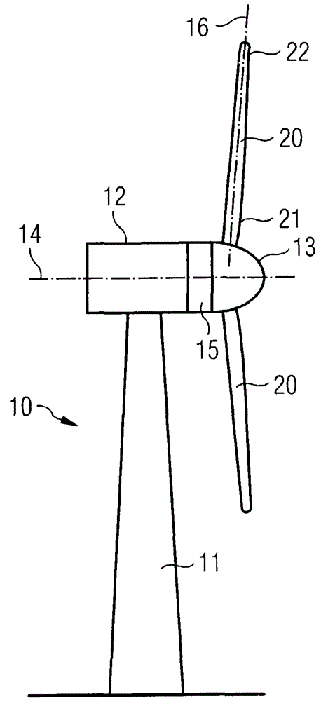
[0088] exist figure 1 In , a wind turbine 10 is shown. The wind turbine 10 includes a nacelle 12 and a tower 11 . The nacelle 12 is mounted on top of the tower 11 . The nacelle 12 is rotatably mounted relative to the tower 11 via a yaw bearing. The axis of rotation of the nacelle 12 relative to the tower 11 is called the yaw axis.

[0089] The wind turbine 10 also includes a hub 13 with three rotor blades 20 (two rotor blades 20 in figure 1 shown in ). The hub 13 is rotatably mounted relative to the nacelle 12 via main bearings. The hub 13 is rotatable about an axis of rotation 14 .

[0090] The wind turbine 10 also includes a main shaft connecting the hub 13 and the rotor of the generator 15 . The hub 13 is directly connected to the rotor, as such, the wind turbine 10 is referred to as a gearless direct drive wind turbine. Alternatively, the hub 13 can also be connected to the rotor via a gearbox. This type of wind turbine is known as a gear driven wind turbine.

[...


PUM


Abstract

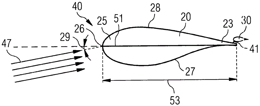
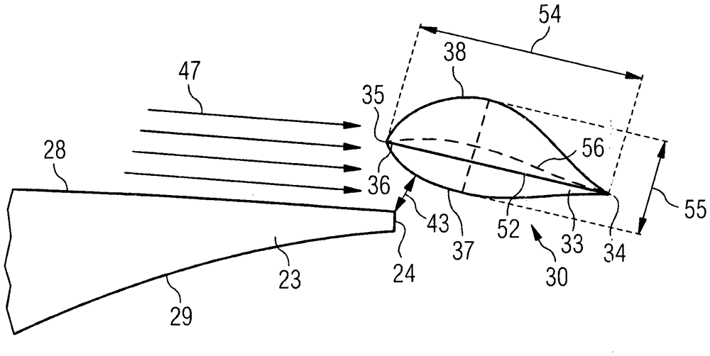
The invention relates to an arrangement (40) comprising a rotor blade (20) of a wind turbine (10), an aerodynamic device (30) and connection means (41) for connecting the aerodynamic device (30) with a trailing edge section of the rotor blade (23). The aerodynamic device (30) comprises an airfoil profile with a pressure side (37), a suction side (38), a trailing edge section (34) and a leading edge section (36). The aerodynamic device (30) is separated from the rotor blade (20) by a slot (42) which is smaller than five centimeters.

Description

[0001] Statement on federally funded development [0002] Development of this invention was supported in part by Contract No. DE-EE0005493 awarded by the US Department of Energy. Accordingly, the US Government has certain rights in this invention. technical field [0003] The invention relates to an arrangement comprising a rotor blade of a wind turbine and an aerodynamic device. The aerodynamic device is connected to the rotor blade by connecting means. Background technique [0004] It is known that the rotor blades of wind turbines can be improved by means of aerodynamic devices such as flaps, plates, etc. On the one hand, such aerodynamic devices can increase the efficiency of wind turbines. On the other hand, such aerodynamics also reduce the noise generated by the air flow over the rotor blades. [0005] Typically, aerodynamics increase the lift of the rotor blades, which is beneficial to wind turbines in general. However, a disadvantage of increasing the lift of t...

Claims


Application Information

Patent Timeline
Patent Type & Authority Applications(China)
IPC IPC(8): F03D1/06F03D11/00
CPCF03D1/0633F03D1/0641F03D1/0675F05B2240/122F05B2250/183F05B2240/305F05B2240/3062Y02E10/72
Inventor P·B·恩沃尔森A·O·扎莫拉罗德里格斯
Owner SIEMENS ENERGY INC
Learn More