A device that utilizes the kinetic energy of flowing water to generate electricity

A kinetic energy and equipment technology, applied in the field of small power generation devices, can solve the problems of low cost, high construction cost, and failure to achieve energy saving, and achieve the effects of low cost, convenient use, and energy saving in use

Inactive Publication Date: 2017-11-14
SHANDONG AGRICULTURAL UNIVERSITY
View PDF4 Cites 0 Cited by
  • Summary
  • Abstract
  • Description
  • Claims
  • Application Information

AI Technical Summary

Problems solved by technology

[0003] In order to overcome the existing small generators that use power machinery (such as diesel engines and gasoline engines) as driving power, due to the need to use primary energy, the effect of energy saving cannot be achieved, and the existing hydroelectric power stations, due to the need to build power plants and their Other ancillary facilities have high construction costs and are not suitable for single family use. The present invention provides a rotor that does not need power machinery (such as diesel engines and gasoline engines) to drive generators to save energy, and it is not like ordinary hydraulic power. The power station needs to establish complex supporting facilities to achieve low cost. It can be installed anywhere near the river according to the needs, and can automatically adjust the working state according to the change of the water level and depth of the river. Under the action of the kinetic energy of the flowing river, the relevant With the cooperation of the mechanism, the rotor of the generator can rotate so that the generator can generate electricity. It is a kind of equipment that uses the kinetic energy of flowing water to generate electricity for families living along the river.

Method used


Image

  • A device that utilizes the kinetic energy of flowing water to generate electricity

Examples


Embodiment Construction

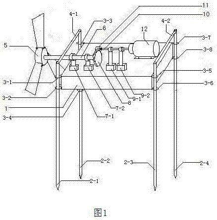
[0016] figure 1 Shown in, a kind of equipment that utilizes flowing water kinetic energy to generate electricity, consists of buoyancy tank 1, guide fixed rod 2-1, 2-2, 2-3, 2-4, guide ring 3-1, 3-2, 3-3 , 3-4, 3-5, 3-6, 3-7, 3-8, connecting rod 4-1, 4-2, water wheel blade disc 5, drive shaft 6, first bearing assembly 7-1, 7 -2, driving gear 8, second bearing assembly 9-1, 9-2, driven shaft 10, driven gear 11 and generator 12 constitute, floating tank 1, guide fixed rod 2-1, 2-2, 2 -3, 2-4, guide ring 3-1, 3-2, 3-3, 3-4, 3-5, 3-6, 3-7, 3-8, connecting rod 4-1, 4-2 , water wheel blade disc 5, driving shaft 6, first bearing assembly 7-1, 7-2, driving gear 8, second bearing assembly 9-1, 9-2, driven shaft 10, driven gear 11 are metal There are eight guide rings divided into four groups, wherein one group of guide rings 3-1, 3-2 is installed on the upper and lower parts of the left outer front end of the pontoon 1, and the second group of guide rings 3-3, 3-4 is installed on the...


PUM


Abstract

A device for generating power through kinetic energy of flowing water is composed of a floating box, guiding and fixing rods, guiding rings, connecting rods, a water wheel blade disk, a driving shaft, a first bearing assembly, a driving gear, a second bearing assembly, a driven shaft, a driven gear and a power generator. The eight guiding rings are divided into four sets and installed at the upper ends and the lower ends of the left side and the right side of the floating box respectively. The four guiding and fixing rods are sleeved with the four sets of guiding rings respectively. The two connecting rods are installed at the upper ends of the four guiding and fixing rods respectively. The water wheel blade disk is installed at the left front end of the driving shaft. The driving gear is installed at the right front end of the driving shaft. The driven gear is installed at the left front end of the driven shaft. The driving shaft and the driven shaft are sleeved with a bearing inner ring of the first bearing assembly and a bearing inner ring of the second bearing assembly respectively. The left front end of a rotor shaft of the power generator is installed at the right front end of the driven shaft. The driving shaft, the driving gear, the first bearing assembly, the second bearing assembly, the driven shaft, the driven gear and the power generator are installed at the outer upper end of the floating box. No matched facilities need to be established for the device for generating power through kinetic energy of the flowing water, and disposable energy does not need to be used.

Description

technical field [0001] The invention relates to a small power generation device, especially does not need power machinery (such as diesel engine, gasoline engine) to drive the rotor of the generator to achieve the purpose of saving energy, and does not need to establish complex supporting facilities like ordinary hydropower stations, so that the cost is low. It can be installed anywhere near the river according to the needs, and can automatically adjust the working state according to the change of the water level and depth of the river. Under the action of the kinetic energy of the flowing river water, with the cooperation of relevant agencies, the rotor of the generator can rotate so that the generator can generate electric energy , a device that uses the kinetic energy of flowing water to generate electricity for families living along the river. Background technique [0002] At present, the existing small generators that use power machinery (such as diesel engines and gaso...

Claims


Application Information

Patent Timeline
Patent Type & Authority Patents(China)
IPC IPC(8): F03B13/00F03B11/00
CPCY02E10/20
Inventor 刘经强刘乾宇
Owner SHANDONG AGRICULTURAL UNIVERSITY
Why Eureka
Try Eureka