Eureka AIR delivers breakthrough ideas for toughest innovation challenges, trusted by R&D personnel around the world.

Offshore wind turbine foundation and construction mechanism thereof

A technology for offshore wind turbines and wind turbine foundations, applied in infrastructure engineering, construction, etc., can solve problems that affect the smooth construction of wind turbine foundations, increase construction costs, and affect construction efficiency, and achieve simple structure, improved efficiency and reliability, and operability strong effect

Active Publication Date: 2015-11-18
CHINA ENERGY ENG GRP GUANGDONG ELECTRIC POWER DESIGN INST CO LTD
View PDF7 Cites 1 Cited by
  • Summary
  • Abstract
  • Description
  • Claims
  • Application Information

AI Technical Summary

Problems solved by technology

[0002] In the current wind turbine foundation forms such as jacket, underwater three-pile and above-water three-pile, the construction sequence of laying pipe piles first, and then installing the wind turbine foundation is adopted. Due to errors in the construction of pipe piles, when the error exceeds the specified range, it will be Will affect the smooth construction of fan foundation
For example, when the construction position of the pipe pile deviates from the predetermined installation position by a large distance, the wind turbine foundation cannot be smoothly inserted into the pipe pile. At this time, the pile will be re-drilled or other special offshore treatment will be carried out, which will seriously affect the construction efficiency and increase the construction cost.
In addition, when large-scale construction is carried out, it is difficult to avoid the phenomenon that the pipe pile deviates from the allowable construction error range

Method used


Image

  • Offshore wind turbine foundation and construction mechanism thereof
  • Offshore wind turbine foundation and construction mechanism thereof
  • Offshore wind turbine foundation and construction mechanism thereof

Examples


Embodiment Construction

[0039] Embodiments of the present invention are described in detail below:

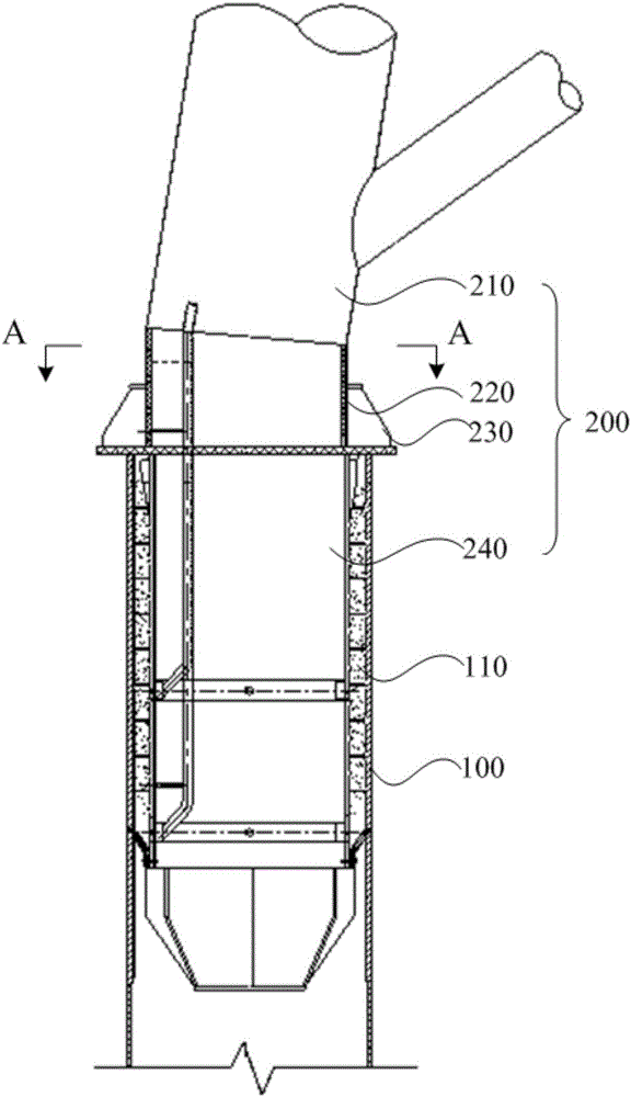
[0040] Such as figure 1 As shown, an offshore wind turbine foundation 200 is fixed in a pipe pile 100 with an opening, and includes a first main body 210, a connecting plate 230 and a second main body 240 arranged in sequence from top to bottom, and the first main body 210 is a supporting structure The main body part, the second main body 240 is a grouting connecting section part, one side of the connecting plate 230 is connected with the first main body 210 , and the other side is connected with the second main body 240 . The pipe pile 100 is fixed on the seabed, and the end of the second body 240 away from the connecting plate 230 extends into the opening of the pipe pile 100 and is fixedly connected with the pipe pile 100 . When the pipe pile 100 deviates from the preset installation position and its deviation exceeds the allowable construction error, it will affect the smooth installation of the ...


PUM


Abstract

The invention discloses an offshore wind turbine foundation which is fixed into pipe columns with openings. The offshore wind turbine foundation comprises a first body, a connecting plate and a second body which are sequentially arranged from top to bottom. One side of the connecting plate is connected with the first body, and the other side of the connecting plate is connected with the second body. The ends, away from the connecting plate, of the second body extend into the openings and are connected with the pipe columns. When the pipe columns are deflected from the preset installation position and the deflection of the pipe columns exceeds the permitted construction error, the second body can be deflected from the connecting plate by a certain degree so that the second body can be smoothly inserted and fixed into the pipe columns. The offshore wind turbine foundation is simple in structure and high in operability, the situation that the deflection permitted column sinking error is large can be rapidly remedied, the smooth installation of the offshore wind turbine foundation can be ensured, and the offshore construction installation efficiency and reliability are improved; the pipe columns which are large in construction error do not need to be specially processed, and the economic benefits of the offshore wind turbine foundation are good.

Description

technical field [0001] The invention relates to the technical field of offshore wind turbine foundations, in particular to an offshore wind turbine foundation and a construction method thereof. Background technique [0002] In the current wind turbine foundation forms such as jacket, underwater three-pile and above-water three-pile, the construction sequence of laying pipe piles first, and then installing the wind turbine foundation is adopted. Due to errors in the construction of pipe piles, when the error exceeds the specified range, it will be It will affect the smooth construction of fan foundation. For example, when the construction position of the pipe pile deviates from the predetermined installation position by a large distance, the wind turbine foundation cannot be smoothly inserted into the pipe pile. At this time, the pile will be re-drilled or other special offshore treatment will be carried out, which will seriously affect the construction efficiency and increas...

Claims


Application Information

Patent Timeline
Patent Type & Authority Applications(China)
IPC IPC(8): E02D27/44E02D27/52
Inventor 元国凯钱可弭刘晋超何小华杨扬汤东升戎晓洪毕明君
Owner CHINA ENERGY ENG GRP GUANGDONG ELECTRIC POWER DESIGN INST CO LTD
Why Eureka
Eureka Blog
Learn More