Inner Hollow Bending Injection Mold

An injection mold and bending technology, which is applied to the field of hollow-bending injection molds, can solve the problems of high production cost, reduced production efficiency of injection molded parts, complicated operation, etc., and achieves the effects of simple production, improved injection molding efficiency, and easy operation.

Active Publication Date: 2018-04-17
北京金马模具制品有限公司
View PDF5 Cites 0 Cited by
  • Summary
  • Abstract
  • Description
  • Claims
  • Application Information

AI Technical Summary

Problems solved by technology

[0005] The purpose of the present invention is to provide an inner hollow bending injection mold to solve the technical problems of high production cost, complicated operation and reduced production efficiency of injection molded parts in the prior art

Method used


Image

  • Inner Hollow Bending Injection Mold
  • Inner Hollow Bending Injection Mold

Examples


Embodiment Construction

[0027] The technical solutions of the present invention will be clearly and completely described below in conjunction with the accompanying drawings. Apparently, the described embodiments are part of the embodiments of the present invention, but not all of them. Based on the embodiments of the present invention, all other embodiments obtained by persons of ordinary skill in the art without making creative efforts belong to the protection scope of the present invention.

[0028] In the description of the present invention, it should be noted that the terms "center", "upper", "lower", "left", "right", "vertical", "horizontal", "inner", "outer" etc. The indicated orientation or positional relationship is based on the orientation or positional relationship shown in the drawings, and is only for the convenience of describing the present invention and simplifying the description, rather than indicating or implying that the referred device or element must have a specific orientation, ...


PUM


Abstract

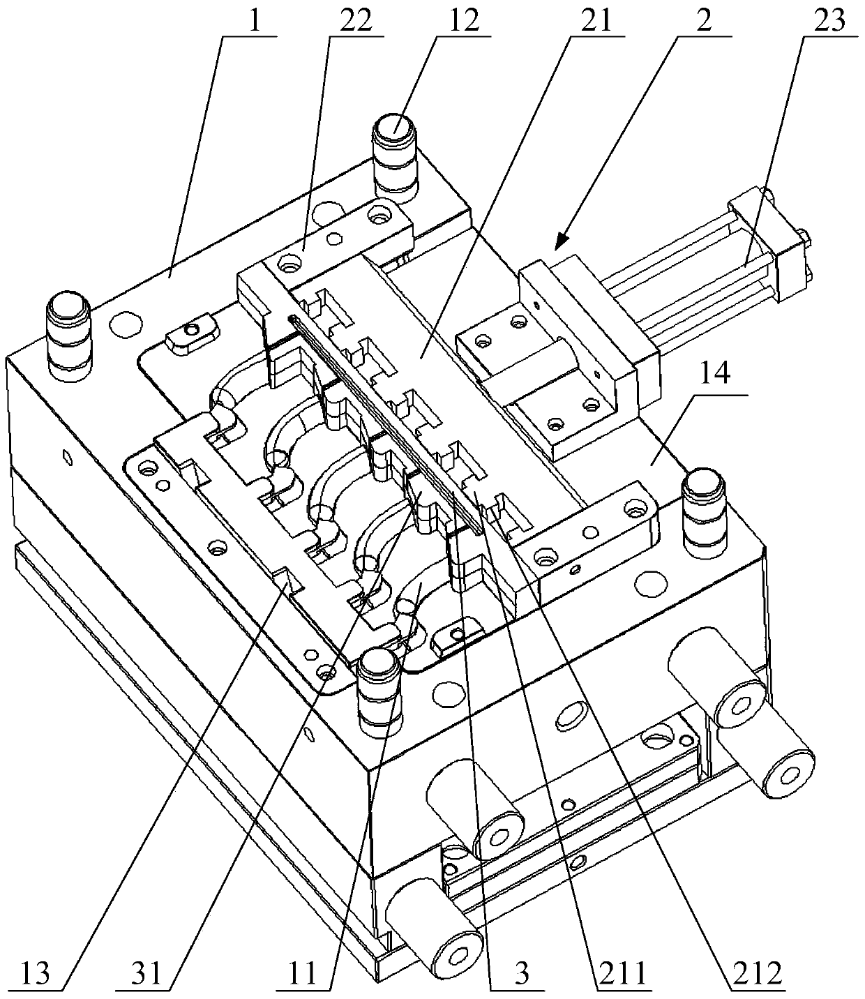
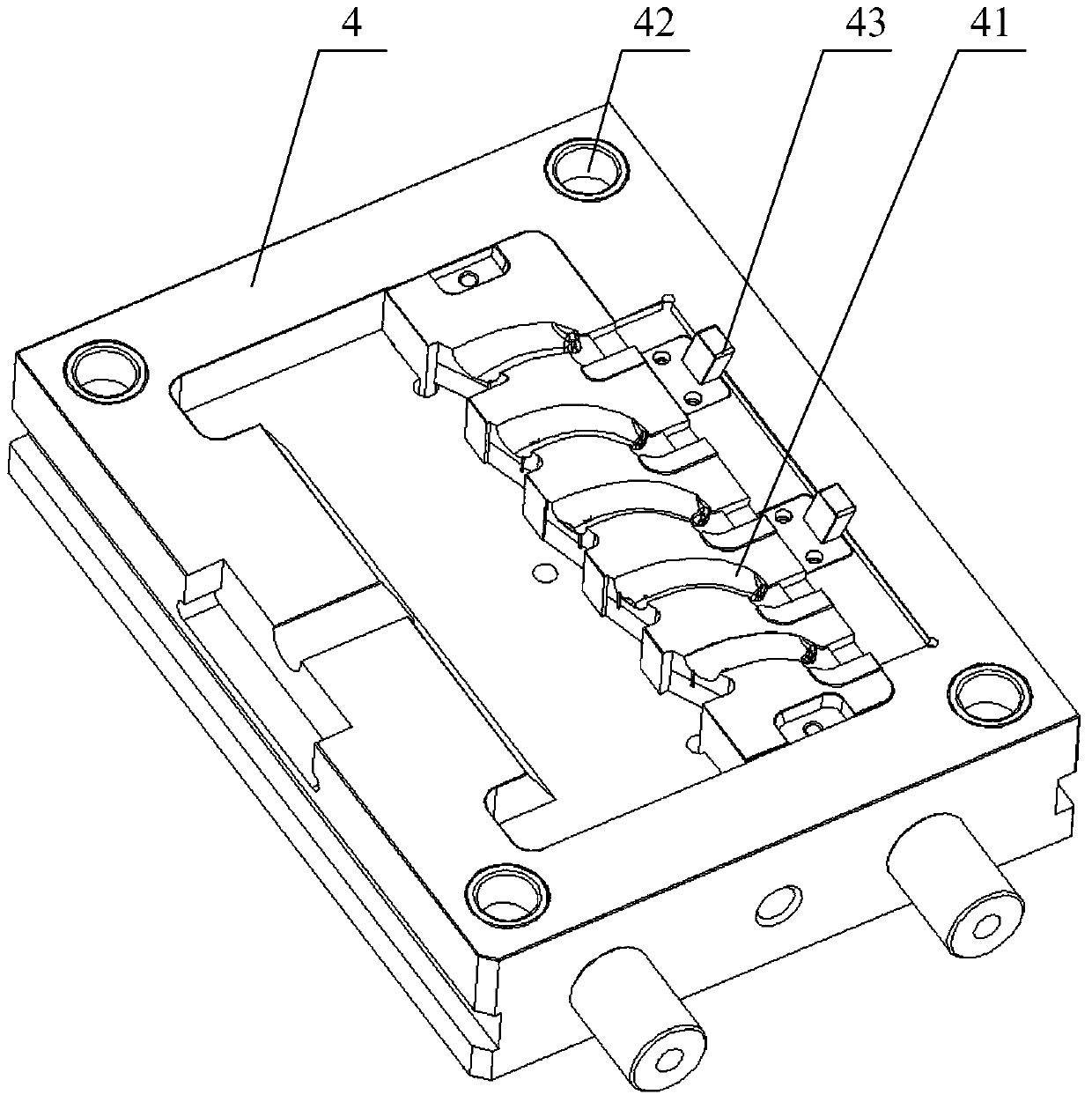
The invention relates to the technical field of molds, in particular to a hollow bent injection mold. The hollow bent injection mold comprises a movable mold, a fixed mold, a core baffle and a sliding component. First grooves are formed in the movable mold, second grooves are formed in the fixed mold, the first grooves and the second grooves form cavities, and cores are arranged in the cavities. The core baffle and the sliding component are both arranged on the movable mold, and the first grooves and the sliding component are located on the two sides of the core baffle. Through holes through which the cores penetrate are formed in the core baffle. One end of the core penetrates through the through holes to be in rotary connection with the sliding component, the core baffle is used for retaining injection-molded parts obtained after injection molding, and the sliding component is used for moving the cores. According to the hollow bent injection mold, the cores are in rotary connection with the sliding component, so that the cores are separated out along the first grooves, the mold core pulling motion achieved through complex curvilinear motion trajectories is avoided, and the mold is simple to manufacture, easy and convenient to operate and capable of improving injection molding efficiency.

Description

technical field [0001] The invention relates to the technical field of molds, in particular to an inner hollow bending injection mold. Background technique [0002] Injection mold is a tool for producing rubber products, and it is also a tool for giving rubber products complete structure and precise dimensions. [0003] The injection mold in the related art is made up of two parts, a movable mold and a fixed mold. The movable mold is installed on the movable template of the injection molding machine, and the fixed mold is installed on the fixed template of the injection molding machine. The movable mold and the fixed mold are bonded to form a core channel, and two half cores are respectively inserted from both ends of the core channel and bonded together to form a core. When the molten plastic is injected into the cavity from the burner sleeve through injection molding, after cooling and forming, the movable mold is separated from the fixed mold, and then the two half-cores...

Claims


Application Information

Patent Timeline
Patent Type & Authority Patents(China)
IPC IPC(8): B29C45/40B29C45/26
CPCB29C45/261B29C45/40B29C2045/4068
Inventor 刘立新赵天柱赵忠民
Owner 北京金马模具制品有限公司
Why Eureka
Try Eureka