Tool fixture and process for machining measuring orifice plate part

A tooling fixture and flow-measuring orifice technology, which is applied in metal processing machinery parts, manufacturing tools, metal processing equipment, etc., can solve the problem of large parallelism errors on both ends of the parts, unguaranteed technical requirements of parts, and geometric accuracy errors. Large and other problems, to achieve the effect of improving processing efficiency, shortening processing cycle, and reducing vibration

Inactive Publication Date: 2015-11-18
GUIZHOU CHITIANHUA ZHENGTAI ENG
View PDF5 Cites 2 Cited by
  • Summary
  • Abstract
  • Description
  • Claims
  • Application Information

AI Technical Summary

Problems solved by technology

[0010] The purpose of the present invention is to provide a fixture and processing technology for processing flow measuring orifice parts, so as to solve the problem of poor rigidity of the parts, easy deformation of the parts during processing, and parallelism between the two ends of the parts in the processing of the existing flow measuring orifice parts. Large precision error, extremely low processing efficiency, large processing dimensional tolerance and geometric accuracy error, and the technical requirements of parts cannot be guaranteed.

Method used


Image

  • Tool fixture and process for machining measuring orifice plate part
  • Tool fixture and process for machining measuring orifice plate part
  • Tool fixture and process for machining measuring orifice plate part

Examples


Embodiment Construction

[0025] In order to make the objectives, technical solutions and advantages of the present invention clearer, the present invention will be further described in detail below in conjunction with the accompanying drawings.

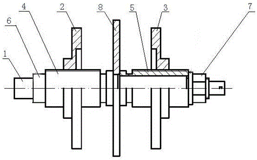
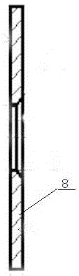
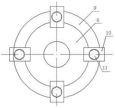
[0026] Combine figure 1 , figure 2 with image 3 , The embodiment of the present invention provides a tooling fixture for processing flow measuring orifice plate parts, including:

[0027] The mandrel 1 further includes a first top plate 2 and a second top plate 3. The first top plate 2 and the second top plate 3 are provided with threaded holes, the mandrel 1 is provided with external threads, the first top plate 2 and the second top plate 3 They are respectively screwed to the mandrel 1, and the first top plate 2 and the second top plate 3 are respectively arranged perpendicular to the mandrel 1.

[0028] The first top plate 2 and the second top plate 3 are both circular plates, and the threaded holes on the two top plates are respectively concentric with their ...


PUM


Abstract

The invention provides a tool fixture and process for machining a measuring orifice plate part, and belongs to the field of machining. The tool fixture comprises a central spindle, and further comprises a first ejection plate and a second ejection plate. The first ejection plate and the second ejection plate are provided with threaded holes. The central spindle is provided with an external thread. The first ejection plate and the second ejection plate are in threaded connection with the central spindle and are perpendicular to the central spindle. The tool fixture and process are used for solving the problems that in the existing process of machining the measuring orifice plate part, due to the poor rigidity of the part, the part is prone to deformation in machining, the parallelism error between the two end faces of the part is large, machining efficiency is extremely low, the machining dimensional tolerance and the geometric accuracy error are large, and the technical requirements of the part can not be met.

Description

Technical field [0001] The invention relates to a tooling fixture and belongs to the field of mechanical processing. Background technique [0002] The flow measuring orifice parts are circular concentric thin plates with sharp right-angled edges. They are typical thin plate parts with high technical requirements and are widely used in the company's production. Its working principle is that the fluid flows through the right-angle side of the orifice with higher technical requirements. Through the throttling effect of the orifice, the flow rate increases and the static pressure decreases, so a pressure difference is generated before and after the orifice. The greater the fluid flow, the greater the pressure difference generated, so that the flow can be measured according to the pressure difference. Production practice shows that if any parameter such as the parallelism of the two ends of the orifice plate, the flatness of the upstream end surface of the orifice plate, the surface ...

Claims


Application Information

Patent Timeline
Patent Type & Authority Applications(China)
IPC IPC(8): B23Q3/14
CPCB23Q3/14B23Q2703/10
Inventor 方文欧安伦
Owner GUIZHOU CHITIANHUA ZHENGTAI ENG
Why Eureka
Try Eureka