Tool-die steel plate straightening machine
A straightening machine and tooling technology, which is applied in the field of tooling steel plate straightening machine, can solve the problem that the adjustment of the roll gap opening cannot meet the adjustment needs, and achieve the effect of improving the forming rate of one time and improving the straightening accuracy
- Summary
- Abstract
- Description
- Claims
- Application Information
AI Technical Summary
Problems solved by technology
Method used
Image

Examples
Embodiment 1
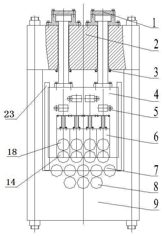
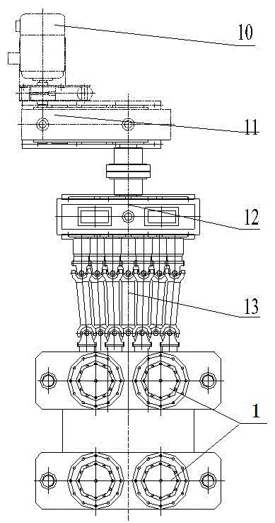
[0028] This embodiment provides a tool and die steel plate straightening machine, such as figure 1 and figure 2 As shown, it includes the main motor 10, and also includes a bracket composed of an upper beam 2, a lower beam 9, and four pillars passing through the four corners of the two. A hollow movable beam 4 is arranged in the bracket, and the upper beam 2 is symmetrically arranged in four directions. There are four hydraulic load cylinders 1, the piston rod of hydraulic load cylinder 1 runs through the upper beam 2 in the vertical direction of the upper beam 2 and is rigidly connected with the movable beam 4, and the four hydraulic load cylinders 1 are symmetrically arranged in a square, and their piston rods and The movable crossbeam 4 is rigidly connected, which is conducive to improving the stress condition of the frame.
[0029] There are multiple sets of pressing mechanisms 5 horizontally arranged above the movable beam 4, and the bottom of each pressing mechanism 5 ...
Embodiment 2
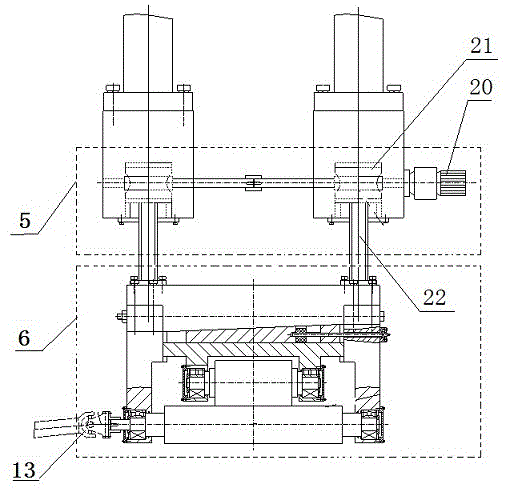
[0034] In this embodiment, the depressing mechanism 5 is described in detail, as Figure 4 As shown, the pressing mechanism 5 includes a worm 20, a worm wheel 21 with a nut in the center, and a screw 22. The worm 20 traverses through the beam wall of the movable beam 4 and is installed in cooperation with the worm wheel 21. The worm wheel 21 is arranged horizontally, and the screw 22 The nut that penetrates the center of the worm wheel 21 along the vertical direction, and the lower end of the screw mandrel 22 is rigidly connected with the composite roller system 6 .
[0035] combine image 3 and Figure 4 , the depressing mechanism 5 is used to adjust the up and down movement of the compound roller system 6. This structure in the present embodiment is realized according to the following process: the worm screw 20 is rotated, and the worm screw 20 only rotates and does not move in the axial direction. At this time, The worm wheel 21 matched with it starts to rotate in the hor...
Embodiment 3
[0038] In this embodiment, the compound roll system 6 is further described, as Figure 5 As shown, the composite roll system 6 includes two side plates 15 vertically opposite to each other. An upper plate 16 is fixed horizontally on the upper parts of the two side plates 15, and an upper straightening roller 14 is installed on the lower parts of the two side plates 15 horizontally. The middle part of the side plate 15 is horizontally equipped with a backup roller bearing seat 17, so that the backup roller bearing seat 17 moves up and down along the side plate 15, and the lower part of the backup roller bearing seat 17 is equipped with an upper backup roller 18;
[0039] A pre-tightening inclined block 19 is installed between the back-up roller bearing seat 17 and the upper plate 16. The lower surface of the upper plate 16 and the upper surface of the pre-tightening inclined block 19 are inclined surfaces parallel to each other. The upper surface of the back-up roller bearing se...
PUM
 Abstract
Description
Claims
Application Information
 - R&D
- Intellectual Property
- Life Sciences
- Materials
- Tech Scout
- Unparalleled Data Quality
- Higher Quality Content
- 60% Fewer Hallucinations
Browse by: Latest US Patents, China's latest patents, Technical Efficacy Thesaurus, Application Domain, Technology Topic, Popular Technical Reports.
© 2025 PatSnap. All rights reserved.Legal|Privacy policy|Modern Slavery Act Transparency Statement|Sitemap|About US| Contact US: help@patsnap.com