Suspension noise-reduction motor
A suspension-type, noise-reducing technology, applied to electrical components, electromechanical devices, electric components, etc., can solve problems affecting the performance of the vacuum cleaner, the wind blocking of the main body of the motor, etc., and achieve substantial characteristics, quiet working environment, and noise reduction. Effect
- Summary
- Abstract
- Description
- Claims
- Application Information
AI Technical Summary
Problems solved by technology
Method used
Image
Examples
Embodiment 1
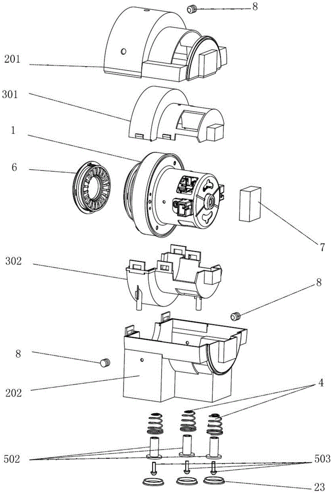
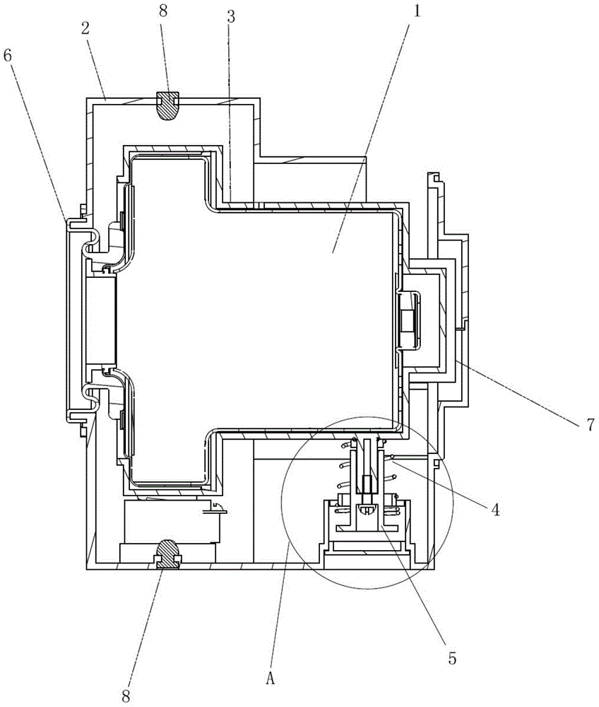
[0063] Please refer to figure 1 and figure 2 , figure 1 and figure 2 They are respectively the exploded schematic diagram and the assembled structure schematic diagram of the suspension noise reduction motor provided in this embodiment. The present invention provides a suspension type noise reduction motor, comprising a motor body 1 and a motor cover 2 at least partially containing the motor body 1, a sealing ring 6 is set on the air inlet 101 of the motor body, and the bottom of the motor body 1 is suspended, so that The main body of the motor 1 is "suspended" in the axial direction.
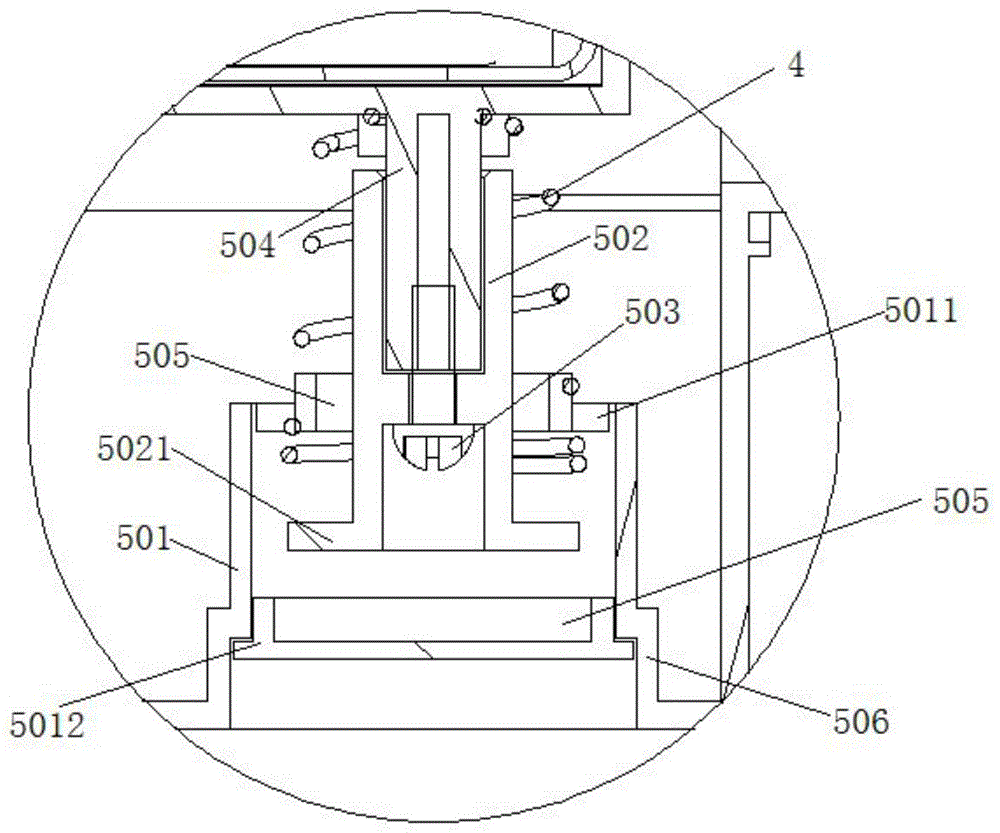
[0064] At least one elastic mechanism 4 is provided between the motor body 1 and the motor cover 2. The elastic mechanism 4 provides support or pulling force to the motor body 1 to offset the gravity of the motor body 1. The elastic mechanism 4 makes the motor body 1 "suspend" in the radial direction stand up.
[0065] In order to prevent the motor body 1 from colliding with the motor co...
Embodiment 2
[0075] Please refer to Figure 4 to Figure 6 , this embodiment discloses another implementation of the suspension noise reduction motor, the difference between this embodiment and Embodiment 1 is as follows:
[0076] The limit mechanism 5 is sleeved on the support frame 9, and the support frame 9 is fixed on the motor cover 2, and the support frame 9 can be fixed on the motor cover 2 by screwing. One end of the elastic mechanism 4 is fixed on the motor, and the other end is fixed on the support frame 9 through the support frame rubber 901. A limiting cavity 10 is formed between the support frame 9 and the motor cover 2, and the support frame is fixed to the motor cover by screws 902. superior. The limit mechanism includes a guide post 502, the head of the guide post 5021 is arranged in the limit cavity 10, the tail of the guide post is fixed on the motor, and the limit cavity 10 allows the head of the guide post 5021 to move up and down in the limit cavity 10 reciprocating m...
PUM
 Abstract
Description
Claims
Application Information
 - R&D
- Intellectual Property
- Life Sciences
- Materials
- Tech Scout
- Unparalleled Data Quality
- Higher Quality Content
- 60% Fewer Hallucinations
Browse by: Latest US Patents, China's latest patents, Technical Efficacy Thesaurus, Application Domain, Technology Topic, Popular Technical Reports.
© 2025 PatSnap. All rights reserved.Legal|Privacy policy|Modern Slavery Act Transparency Statement|Sitemap|About US| Contact US: help@patsnap.com


