Wireless power supply device

A technology of wireless power supply and antenna, applied in the direction of circuit devices, electrical components, electromagnetic wave systems, etc., can solve problems such as complex device structures, and achieve the effect of suppressing changes and stabilizing wireless power transmission

Active Publication Date: 2015-11-11
PANASONIC INTELLECTUAL PROPERTY MANAGEMENT CO LTD
View PDF5 Cites 0 Cited by
  • Summary
  • Abstract
  • Description
  • Claims
  • Application Information

AI Technical Summary

Problems solved by technology

Furthermore, as the microwave generator in the wireless power supply device in the prior art, it needs to be composed of a power source that can control the power, which will make the device structure complicated.

Method used


Image

  • Wireless power supply device
  • Wireless power supply device
  • Wireless power supply device

Examples


Embodiment approach 1

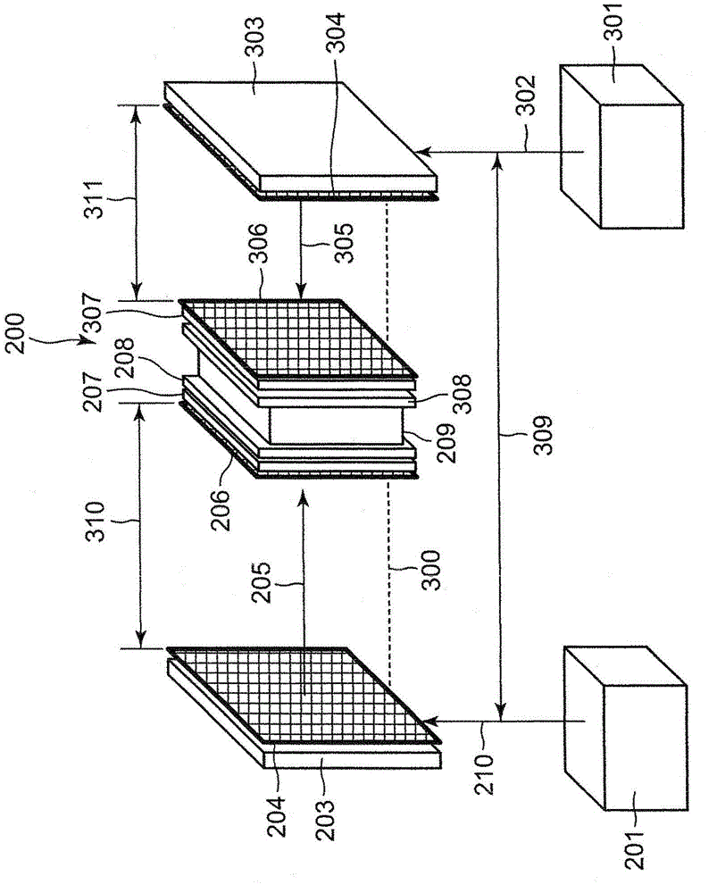
[0049] figure 1 It is a diagram showing the basic configuration of the wireless power feeding device according to Embodiment 1 of the present invention. The first microwave generator 201 that generates electromagnetic waves (microwaves) transmits microwaves to the first power transmission antenna 203 via the first microwave transmission path 202 to supply constant power. As the first microwave transmission path 202, a distributor and a microwave amplifier are included depending on the case. The first microwave 205 is radiated from the power transmission surface 204 of the first power transmission antenna 203 , and the microwave is received by the power reception surface 206 of the first power reception antenna 207 . The first microwave 205 received by the power receiving surface 206 of the first power receiving antenna 207 is power converted in the first power conversion circuit unit 208 , and then power is supplied to the power feeding target unit 209 .

[0050] Similarly,...


PUM


Abstract

A wireless power supply device is capable of supplying constant power without fluctuation in transmission efficiency even when small-sized antennas in which the power fluctuates due to the transmission distance are used. The wireless power supply device includes a first power receiving antenna having a power receiving surface facing a power transmission surface of a first transmission antenna and a second power receiving antenna having a power receiving surface facing a power transmission surface of a second power transmission antenna, both are integrally formed and connected to a power supply target. A direction in which the power receiving surface of the first power receiving antenna faces the power transmission surface of the first power transmission antenna is parallel to a direction in which the power receiving surface of the second power receiving antenna faces the power transmission surface of the second power transmission antenna.

Description

technical field [0001] The present invention relates to a wireless power supply device for wirelessly transmitting and receiving electric power using electromagnetic waves (microwaves). Background technique [0002] In recent years, technological development of transmitting electric power using electromagnetic waves (microwaves) and supplying electric power wirelessly is underway. As an example of a wireless power feeding technology using electromagnetic waves, there is a system that uses microwaves in a frequency band of several hundred kHz to several MHz to utilize coupling or resonance of a magnetic field at a short distance of several meters or less where electromagnetic induction or magnetic resonance is possible. In such a system, a wireless power transmission method in which a power supply device that supplies power is fixed to a power receiving device that supplies power at a fixed position is often used. In addition, in order to wirelessly transmit electric power t...

Claims


Application Information

Patent Timeline
IPC IPC(8): H02J17/00
CPCH02J17/00H02J50/27H02J50/23H02J50/40H02J50/90H02J50/20
Inventor 谷博之
Owner PANASONIC INTELLECTUAL PROPERTY MANAGEMENT CO LTD
Why Eureka
Try Eureka