
Optical surveying and mapping prism adjusting base

A technology for adjusting seat and prism, which is applied in the direction of optics, optical components, installation, etc. It can solve the problems of wasting time and energy for repeated adjustment of reflective prisms, the loss of light intensity reflected by the reflective surface, and no good effect can be obtained, so as to achieve the reflection effect Better stability, less interference, and easier installation and removal

Active Publication Date: 2015-11-11
NANTONG MEELAIN ELECTRIC APPLIANCE CO LTD
View PDF5 Cites 1 Cited by
  • Summary
  • Abstract
  • Description
  • Claims
  • Application Information

AI Technical Summary

Problems solved by technology

[0002] The prism adjustment base generally only has a threaded hole that can be installed with a prism. Under certain surveying and mapping conditions, it is not easy to find the target when the reflection of the prism is disturbed by the surveying and mapping equipment. The repeated adjustment of the reflective prism in the surveying and mapping work wastes a lot of time and energy, especially in the outdoor environment, which needs to be simple and fast
[0003] The intensity of reflected light on the reflective surface of the prism will be lost, and no good effect will be obtained.
In this way, infrared light will be used instead. Although it cannot be observed by naked eyes, it can be observed with the help of instruments. Simple prisms can no longer achieve better functions. It is necessary to modify the surface shape of the prism surface in order to achieve better reflection of infrared rays. Even enhanced infrared

Method used


Image

  • Optical surveying and mapping prism adjusting base
  • Optical surveying and mapping prism adjusting base
  • Optical surveying and mapping prism adjusting base

Examples


Embodiment Construction

[0029] The present invention will now be further described in detail in conjunction with the accompanying drawings and embodiments. These drawings are all simplified schematic diagrams, only illustrating the basic structure of the present invention in a schematic manner, so it only shows the composition related to the present invention.

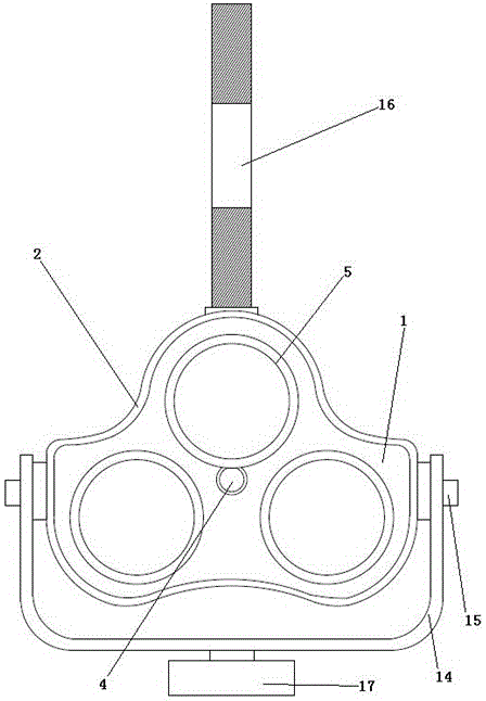
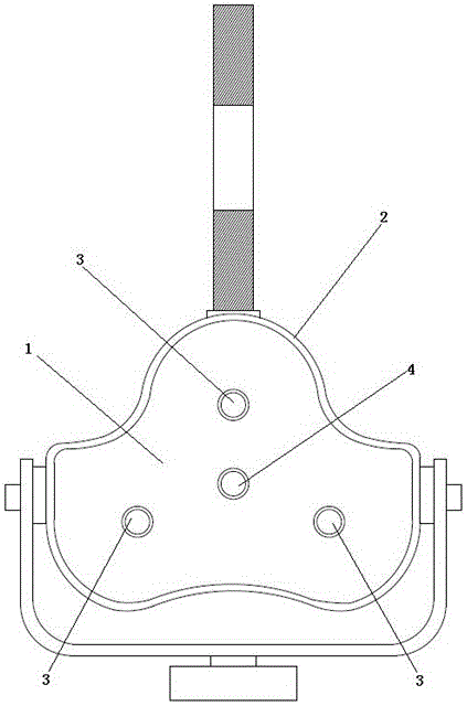
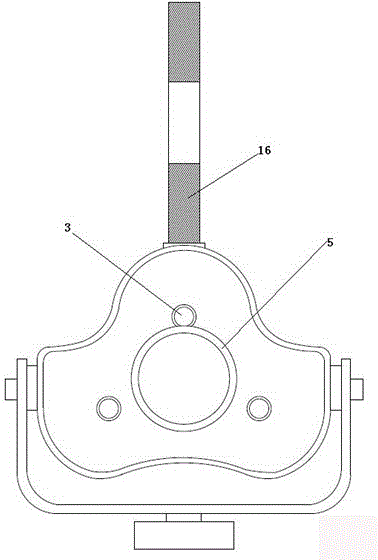
[0030] like Figure 1-5 As shown, a prism adjustment seat for optical surveying and mapping includes: a fixed plate 1, and a guard plate 2 fixed around the circumference of the fixed plate 1, and the fixed plate 1 is provided with three first fixed plates arranged in a character shape. Hole 3, a second fixing hole 4 is provided on the fixing plate 1 in the triangle formed by the connection of the three fixing holes;

[0031] When three first fixed holes 3 on the fixed plate 1 are respectively provided with a prism lens 5 at the same time, the second fixed hole 4 can not be provided with a prism lens 5 now; when a second fixed hole 4 on the fi...


PUM


Abstract

The invention relates to an optical surveying and mapping prism adjusting base which comprises a fixation plate and a guard board fixedly encircling the circumference of the fixation plate. The adjusting base is characterized in that the fixation plate is provided with three first fixation holes arranged like the Chinese character "pin"; the fixation plate in a triangle formed by connecting the three first fixation holes is provided with a second fixation hole; when the three first fixation holes in the fixation plate are respectively provided with a prism unit simultaneously, the second fixation hole cannot be provided with a prism unit; and when the second fixation hole in the fixation plate is provided with the prism unit, the three first fixation holes cannot be provided with the prism unit. Through the arrangement of the three first fixation holes and the second fixation hole, three prism units can form a group to carry out reflection work simultaneously; and through switching, the state that only one prism unit works can also be realized; and thus reflection condition flexibility of the surveying and mapping work is better.

Description

technical field [0001] The invention relates to a precision surveying and mapping optical instrument, in particular to a prism adjusting base for optical surveying and mapping. Background technique [0002] The prism adjustment base generally only has a threaded hole that can be installed with a prism. Under certain surveying and mapping conditions, it is not easy to find the target when the reflection of the prism is disturbed by the surveying and mapping equipment. The repeated adjustment of the reflective prism in surveying and mapping wastes a lot of time and energy, especially in outdoor environments, which need to be simple and fast. [0003] The reflected light intensity of the reflective surface of the prism will be lost, and no good effect will be obtained. In this way, infrared light will be used instead. Although it cannot be observed by naked eyes, it can be observed with the help of instruments. Simple prisms can no longer achieve better functions. It is necess...

Claims


Application Information

Patent Timeline
Patent Type & Authority Applications(China)
IPC IPC(8): G02B7/18
Inventor 薛文英
Owner NANTONG MEELAIN ELECTRIC APPLIANCE CO LTD
Learn More