
Low drop-out transmission valve sealing control method and low drop-out transmission valve

A technology of sealing control and transmission valve, which is applied in the sealing control of low differential pressure transmission valve, the sealing control method of low differential pressure transmission valve and the field of low differential pressure transmission valve, which can solve the problems of unstable air pressure, increased manufacturing cost, shortened motor life, etc. , to achieve the effect of extending service life, reducing design requirements and reducing costs

Active Publication Date: 2015-11-11
SHENZHEN XINYUREN TECH
View PDF6 Cites 2 Cited by
  • Summary
  • Abstract
  • Description
  • Claims
  • Application Information

AI Technical Summary

Problems solved by technology

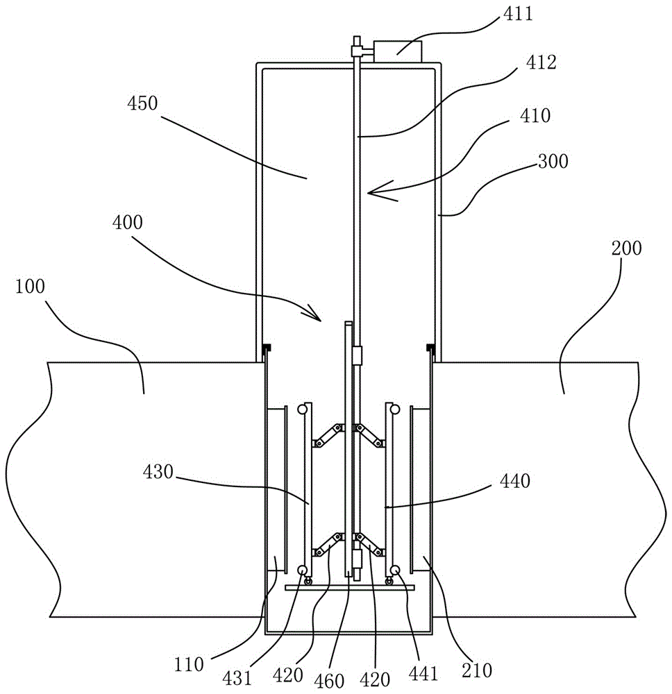
Existing reciprocating driving device 410 generally adopts motor to drive reciprocating driving door 460 through nut screw structure or rack and pinion to realize opening and closing of airtight doors 430, 440. If the airtight door 430, 440 is kept sealed for a long time by means of motor drive, it is easy to shorten the life of the motor (the motor burns out)
In order to solve this problem, people have designed a cylinder to replace the motor to drive the reciprocating drive door 400, but due to the instability of the air pressure, the sealing effect of the airtight doors 430 and 440 will be affected. Although the opening and closing mechanism 420 can improve the sealing effect, the design requirements and material requirements for the airtight door opening and closing mechanism 420 are also very high, which increases the manufacturing cost; It has a good sealing effect, but because the oil cylinder needs a complete set of hydraulic system to match, the cost is very high

Method used


Image

  • Low drop-out transmission valve sealing control method and low drop-out transmission valve
  • Low drop-out transmission valve sealing control method and low drop-out transmission valve
  • Low drop-out transmission valve sealing control method and low drop-out transmission valve

Examples


Embodiment Construction

[0030] In the description of the present invention, it should be understood that the orientation or positional relationship indicated by the terms "center", "upper", "lower", "front", "rear", "left", "right" etc. are based on The orientation or positional relationship shown in the drawings is only for the convenience of describing the present invention and simplifying the description, and does not indicate or imply that the referred device or element must have a specific orientation, be constructed and operated in a specific orientation, and therefore cannot be understood as Limitations on the Invention. In addition, the terms "first" and "second" are used for descriptive purposes only, and should not be understood as indicating or implying relative importance.

[0031] In the description of the present invention, it should be noted that unless otherwise specified and limited, the terms "installation", "connection" and "connection" should be understood in a broad sense, for ex...


PUM


Abstract

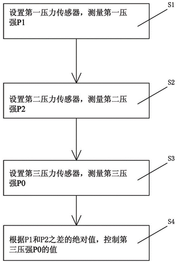
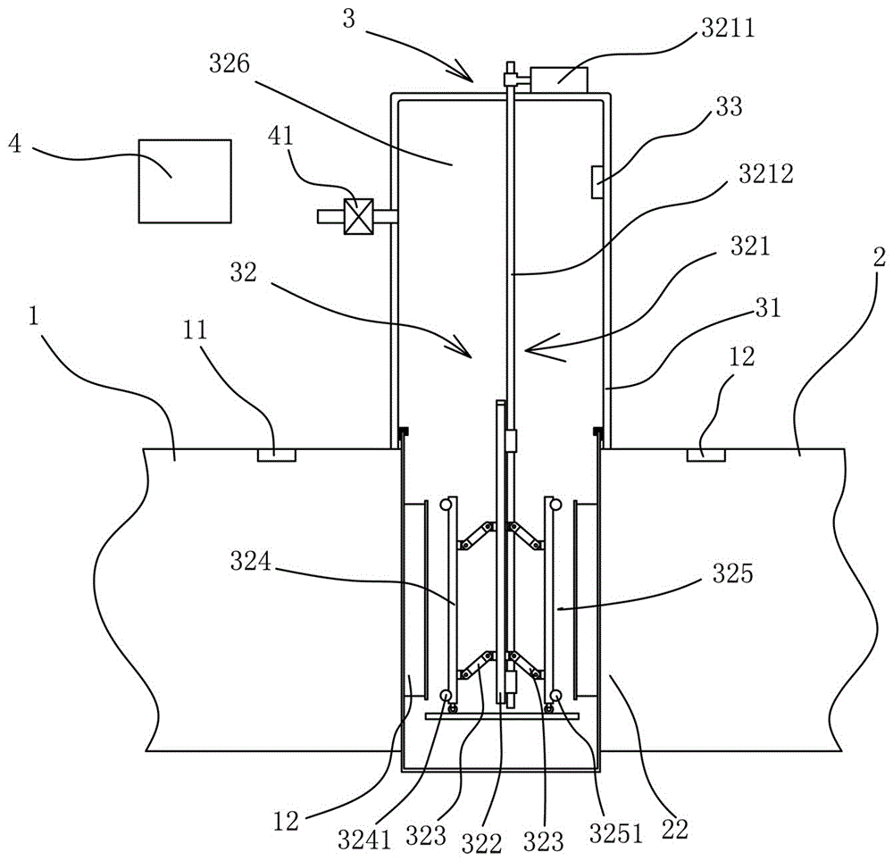
The invention discloses a low drop-out transmission valve sealing control method and a low drop-out transmission valve. According to the method, a transmission valve arranged between two adjacent working boxes and used for enabling the working boxes to be connected or disconnected is arranged, a first pressure sensor used for measuring first pressure P1 is arranged in the first working box, a second pressure sensor used for measuring second pressure P2 is arranged in the second working box, a third pressure sensor used for measuring third pressure P0 is arranged in the transmission valve, and a control device is arranged for controlling the state of the third pressure P0 according to the state of the first pressure P1 and the second pressure P2; when P0 is larger than the maximum value (please see the formula in the specification) of P1 and P2, the third pressure P0 is kept unchanged, and a motor is shut off. By the adoption of the low drop-out transmission valve sealing control method and the low drop-out transmission valve, the motor can be protected, and the service life of the motor can be prolonged; meanwhile, the requirement for design of a sealing door opening and closing mechanism can be lowered, and cost can be reduced.

Description

technical field [0001] The invention relates to a sealing control method of a low-pressure differential transmission valve and a low-pressure differential transmission valve, in particular to a sealing control method of a low-pressure differential transmission valve suitable for use in a vacuum tunnel oven for lithium batteries or lithium battery pole pieces and Low differential transfer valve. Background technique [0002] At present, in the production process of new energy materials, it is necessary to bake the new energy materials to remove moisture. For example, the manufacture of lithium-ion battery pole pieces or lithium-ion batteries requires the lithium-ion battery pole pieces or Lithium-ion batteries are deep dried. The most common drying equipment is the internal circulation single box oven, which first puts the baked lithium battery or battery electrode into the vacuum oven, then seals the vacuum oven, and puts it under normal pressure. Next, first heat the bake...

Claims


Application Information

Patent Timeline
IPC IPC(8): F26B21/00F26B15/10F26B25/02
Inventor 杨志明
Owner SHENZHEN XINYUREN TECH
Learn More