Strain gauge attaching device and method for deep-hole shaft pin sensor
A shaft pin sensor and patch device technology, which is applied in the direction of plastic deformation fastening, connecting components, mechanical equipment, etc., can solve the problem of inability to ensure accurate positioning of strain gauges, poor connection between the patch and the inner wall of the deep-hole narrow-diameter shaft pin, etc. problems, to achieve the effect of improving placement efficiency and placement accuracy, improving placement efficiency, and facilitating smooth entry
- Summary
- Abstract
- Description
- Claims
- Application Information
AI Technical Summary
Problems solved by technology
Method used
Image
Examples
Embodiment 1
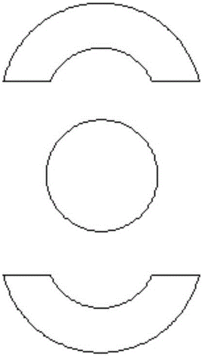
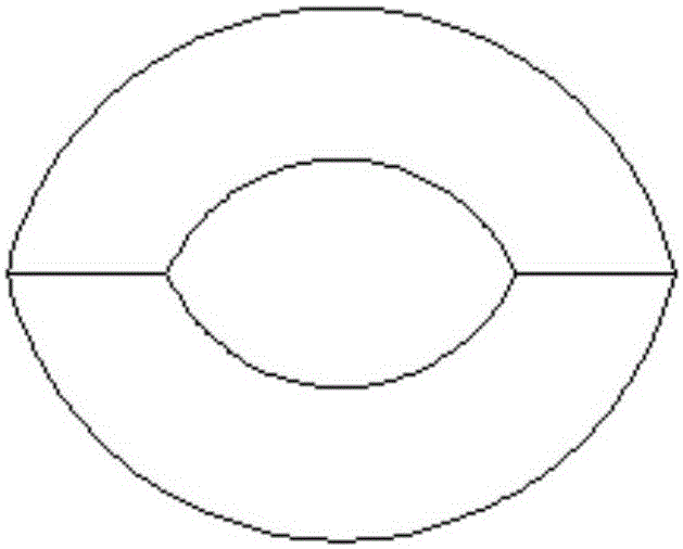
[0052] Such as figure 1 , figure 2 , image 3 with Figure 4 As shown, a deep-hole shaft pin sensor patch device includes two arc-shaped plates and a rod core. The materials of the arc-shaped plates and the rod core are both martensitic precipitation-hardening stainless steel of the brand SS-17-4PH; the arc The surface hardness of the shaped plate and the rod core are both HRC33; the arc-shaped plate is in the shape of an arc tile, which includes an inner arc surface, an outer arc surface, and two transitional surfaces between the inner arc surface and the outer arc surface; the outer arc surface is rough The degree of roughness is 0.4; the roughness of the inner arc surface and the surface of the rod core is 0.2; the two transition surfaces on the same arc plate are on the same plane; one end of the rod core is hemispherical, and the cross section of the rod core is circular. The radius of the arc is equal to the radius of the arc on the cross section of the inner arc; th...
Embodiment 2
[0067] Same as Example 1, except that: the surface hardness of the arc-shaped plate and the rod core are both HRC30; the roughness of the outer arc surface is 0.2; the roughness of the inner arc surface and the surface of the rod core is 0.1; the two arc-shaped plates The distance between the transition surfaces of the two arc-shaped plates parallel to each other after the inner arc surface and the outer surface of the rod core is bonded is 8mm, and the diameter of the outer arc-shaped surfaces of the two arc-shaped plates is smaller than the diameter of the deep hole in the deep hole shaft pin sensor 12mm, so that after the rod core extends into the two arc-shaped plates, the two arc-shaped plates can expand radially by 4mm, so that the distance between the inner wall of the deep hole and the outer arc surface of the two arc-shaped plates is 10mm; conversely, when After wrapping the 8mm thick rubber sheet on the two arc-shaped plates, the expansion of the two arc-shaped plates...
Embodiment 3
[0070] Same as Example 1, except that: the surface hardness of the curved plate and the rod core are both HRC29; the roughness of the outer curved surface is 0.2; the roughness of the inner curved surface and the surface of the rod core is 0.4; the two curved plates The distance between the transition surfaces of the two arc-shaped plates parallel to each other after the inner arc surface and the outer surface of the rod core is bonded is 8mm, and the diameter of the outer arc-shaped surfaces of the two arc-shaped plates is smaller than the diameter of the deep hole in the deep hole shaft pin sensor 16mm, so that after the rod core extends into the two arc-shaped plates, the two arc-shaped plates can expand radially by 4mm, so that the distance between the inner wall of the deep hole and the outer arc surface of the two arc-shaped plates is 16mm; conversely, when After wrapping the 10mm thick rubber sheet on the two arc-shaped plates, the expansion of the two arc-shaped plates ...
PUM
| Property | Measurement | Unit |
|---|---|---|
| Thickness | aaaaa | aaaaa |
| Thickness | aaaaa | aaaaa |
| Surface hardness | aaaaa | aaaaa |
Abstract
Description
Claims
Application Information
 - R&D
- Intellectual Property
- Life Sciences
- Materials
- Tech Scout
- Unparalleled Data Quality
- Higher Quality Content
- 60% Fewer Hallucinations
Browse by: Latest US Patents, China's latest patents, Technical Efficacy Thesaurus, Application Domain, Technology Topic, Popular Technical Reports.
© 2025 PatSnap. All rights reserved.Legal|Privacy policy|Modern Slavery Act Transparency Statement|Sitemap|About US| Contact US: help@patsnap.com


