
Simple mechanical arm

A manipulator and a simple technology, applied in the field of manipulators, can solve the problems of poor movement flexibility of the manipulator, influence of the work efficiency of the manipulator, and small range of motion of the manipulator, and achieve the effects of simple structure, low production cost and large range of motion.

Active Publication Date: 2015-11-11
宁波宫铁智能科技有限公司
View PDF6 Cites 13 Cited by
  • Summary
  • Abstract
  • Description
  • Claims
  • Application Information

AI Technical Summary

Problems solved by technology

[0003] Existing manipulators mainly include a plurality of manipulators that are connected in sequence and can move. Each manipulator is movably connected and each manipulator can move freely. This kind of mechanical arm is installed on the rotating device that can rotate circumferentially through the main arm, and the main arm controls its own rotation and circumferential rotation through the control mechanism, which has the following technical problems. 1. The movable joints of the whole manipulator are less, causing the manipulator The range of motion of the robot is small, resulting in poor movement flexibility and low work efficiency of the manipulator; 2. The entire robot arm is large in size, and the structure of controlling each arm joint is relatively complicated, resulting in problems of high cost and high energy consumption. Larger, its movement is relatively slow, and it also has an impact on the working efficiency of the manipulator itself

Method used


Image

  • Simple mechanical arm
  • Simple mechanical arm
  • Simple mechanical arm

Examples


Embodiment Construction

[0065] The following are specific embodiments of the present invention and in conjunction with the accompanying drawings, the technical solutions of the present invention are further described, but the present invention is not limited to these embodiments.

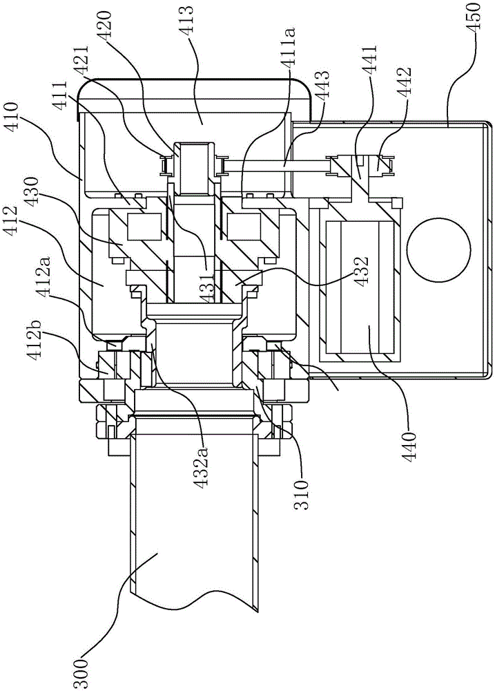
[0066] Such as figure 1 As shown, a simple manipulator of the present invention includes a manipulator assembly 100 connected in sequence, a first control mechanism 200, a forearm 300, a second control mechanism 400, a third control mechanism 500, a main arm 600, a fourth control mechanism 700, a base Seat 800.

[0067] Such as figure 2 As shown, the manipulator assembly 100 includes a mounting base 110 and a pneumatic gripper 120 .

[0068] The mounting base 110 is triangular in shape and has two adjacent mounting surfaces and fixed surfaces adjacent to the two mounting surfaces respectively. The pneumatic gripper 120 is used to clamp and place the workpiece. Mounted on two mounting surfaces.

[0069] Such as image...


PUM


Abstract

The invention provides a simple mechanical arm and belongs to the technical field of mechanical arms. The simple mechanical arm solves the technical problems that an existing mechanical arm is large in size, complex in structure and inflexible to operate. Thee simple mechanical arm comprises a mechanical arm assembly, a first control mechanism, a front arm body, a second control mechanism, a third control mechanism, a main arm, a fourth control mechanism and a base. The mechanical arm assembly is used for clamping workpieces. The first control mechanism controls the mechanical arm assembly to rotate circumferentially and swing. One end of the front arm body is connected with the first control mechanism. The second control mechanism is capable of controlling the main arm body to rotate. The third control mechanism is capable of controlling the second control mechanism to swing in the vertical plane. One end of the main arm body is fixedly connected with the third control mechanism. The fourth control mechanism is capable of controlling the main arm body to swing in the vertical plane. The base is rotatable, and the fourth control mechanism is arranged on the base. Through the four control mechanisms, the mechanical arm can move flexibly in different planes, the simple mechanical arm is wider in movement range and higher in flexibility, and therefore the working efficiency of the mechanical arm is improved.

Description

technical field [0001] The invention belongs to the technical field of manipulators and relates to a simple manipulator. Background technique [0002] The manipulator is an automatic production equipment that replaces people in the industry to complete large-scale and high-quality requirements. It includes a hand and a movement mechanism. The movement mechanism includes multiple connected arms, and various rotations, swings, movements or compound movements are completed through the arms. To achieve the prescribed action, change the position and posture of the grasped object. [0003] Existing manipulators mainly include a plurality of sequentially connected and movable manipulators, each manipulator is movably connected and each manipulator can move freely. This kind of mechanical arm is installed on the rotating device that can rotate circumferentially through the main arm, and the main arm controls its own rotation and circumferential rotation through the control mechanis...

Claims


Application Information

Patent Timeline
IPC IPC(8): B25J9/04B25J13/00
Inventor 朱建群
Owner 宁波宫铁智能科技有限公司
Learn More