
Adjustable lifting sheep safety frame

A restraining frame and lifting technology, which is used in medical science, veterinary instruments, and animal restraint instruments, etc., can solve the problems of easy damage to the sheep body, troublesome use, etc., and achieves easy processing and manufacturing, convenient operation, and convenient fixing and lifting. Effect

Inactive Publication Date: 2017-03-01
INST OF ANIMAL HUSBANDRY & VETERINARY MEDICINE HENAN ACAD OF AGRI SCI
View PDF10 Cites 0 Cited by
  • Summary
  • Abstract
  • Description
  • Claims
  • Application Information

AI Technical Summary

Problems solved by technology

[0005] In view of the disadvantages of troublesome use and easy damage to the sheep's body in the existing sheep safety frame, the present invention provides a flexible and easy-to-use sheep safety frame

Method used


Image

  • Adjustable lifting sheep safety frame
  • Adjustable lifting sheep safety frame
  • Adjustable lifting sheep safety frame

Examples


Embodiment 1

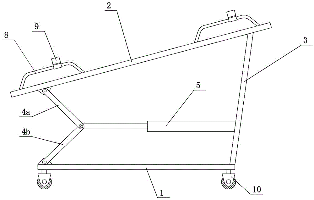
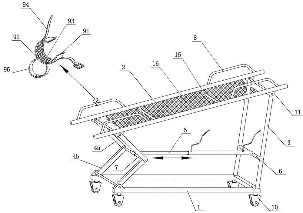
[0020] Example 1: see figure 1 and figure 2 , the first adjustable lift sheep restraint frame, including support frame, universal wheel 10, control switch and fixing parts 9 and other components.

[0021] Among them, the support frame includes a bottom beam or a bottom plate 1, a top beam or a top plate 2, a pair of fixed columns 3 on the rear side, and a pair of movable columns on the front side; the upper end of the fixed column 3 is hinged on the side of the top beam or the top plate 2, and the movable columns The upper end of the movable column is hinged on the side of the top beam or the top plate 2, and the lower end of the movable column is hinged on the side of the bottom beam or the bottom plate 1; a support rod 6 is laterally connected between the fixed columns 3 on both sides.

[0022] The folding upright column includes an upper folding rod 4a and a lower folding rod 4b, which are hinged together, and the hinged rotating shaft is a horizontal push-pull rod 7 .

...

Embodiment 2

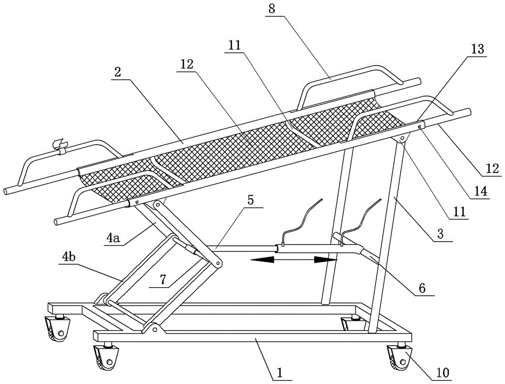
[0026] Embodiment 2: The second adjustable lift sheep restraint frame, see image 3 , On the basis of Example 1, the top beam is designed as a telescopic sleeve structure, and locking bolts are provided. image 3 In the middle, the top beam is a pipe fitting, and the sleeve rod is sleeved on the inner side of the top beam. The auxiliary rod is welded on the sleeve rod. The end of the top beam is provided with a guide groove, and the auxiliary rod is matched and installed in the guide groove, so that the sleeve rod can be prevented from rotating. A connecting rod can also be arranged between the two sleeve rods.

Embodiment 3

[0027] Embodiment 3: The third adjustable elevating sheep restraint frame, see Figure 4 , On the basis of Example 2, the bottom beam is designed as a telescopic sleeve structure, and locking bolts are provided. to increase overall stability.


PUM


Abstract

The invention discloses an adjustable lifting type sheep protecting and fixing frame which comprises a supporting frame, universal wheels, a control switch, fixing pieces and other components. The lower ends of movable stand columns of the supporting frame are hinged to bottom beams or the side part of a bottom plate. A supporting rod is transversely connected between the fixed stand columns on the two sides. Folding stand columns comprise upper folding rods and lower folding rods, wherein the upper folding rods and the lower folding rods are hinged together. A driving mechanism is hinged between the fixed stand columns and a push-pull rod. Lifting of one side of the sheep protecting and fixing frame is achieved through the driving mechanisms, the lifting range is wide, the sheep protecting and fixing frame can descend to the part near the bottom beams the lowest and can ascend to the part with the height similar to that of the fixed stand columns the highest, and thus a sheep can be very conveniently fixed and lifted. Time and labor are saved, and operation is convenient. The limbs of the sheep can be fixed quickly through the fixing pieces, and the sheep legs are protected against damage. The adjustable lifting type sheep protecting and fixing frame is simple in structure, easy to process and manufacture and very suitable for being implemented and popularized.

Description

technical field [0001] The invention belongs to the field of tools for animal husbandry production, in particular to an adjustable elevating sheep restraint frame. Background technique [0002] In large pastures or small sheep farmers, when shearing sheep or giving them vaccinations and medical injections, they usually tie up the four legs of the sheep with ropes, or use multiple people to hold the sheep. , Especially when shearing sheep, it takes a long time to tie the sheep. For pregnant ewes, it is easy to cause miscarriage, and even dead sheep occur, which is a waste of manpower and economic losses. [0003] At present, rapid propagation of high-quality sheep is a necessary way for the rapid development of the sheep industry, and embryo transfer is the most effective and efficient technology for rapid propagation. Sheep embryo transfer needs to be held in sheep, whether it is flushing or transferring embryos, and a convenient and adjustable holding frame is used in prod...

Claims


Application Information

Patent Timeline
Patent Type & Authority Patents(China)
IPC IPC(8): A61D3/00
Inventor 施巧婷白跃宇宁忠山王二耀冯亚杰辛晓玲王鸿周赵洪昌徐照学
Owner INST OF ANIMAL HUSBANDRY & VETERINARY MEDICINE HENAN ACAD OF AGRI SCI
Learn More