
Corn harvester exhaust fan system

A technology of corn harvester and fan system, applied in agricultural machinery and implements, agricultural machinery equipment, threshing equipment, etc., can solve the problems of low waste removal efficiency, complex transmission structure, high cost, etc., to reduce power consumption and simplify transmission structure , the effect of reducing the failure rate

Inactive Publication Date: 2017-11-17
潍坊昌荣机械有限公司
View PDF7 Cites 0 Cited by
  • Summary
  • Abstract
  • Description
  • Claims
  • Application Information

AI Technical Summary

Problems solved by technology

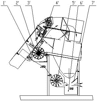
[0004] The miscellaneous fan system with the above structure has the following problems in use. One fan is required for the elevator miscellaneous and the recovery bin, which leads to high cost, complex transmission structure, high failure rate, excessive power consumption, and recovery bin. There is a positive pressure air chamber between the center and the screen, which is easy to block and has low efficiency of waste removal

Method used


Image

  • Corn harvester exhaust fan system
  • Corn harvester exhaust fan system
  • Corn harvester exhaust fan system

Examples


Embodiment Construction

[0029] Examples, as attached figure 1 , Attached figure 2 , Attached image 3 , Attached Figure 4 And Figure 5 As shown, the impurity exhaust fan system of the corn harvester includes an elevator 8 and a peeling frame 9. The main fan bracket 2 is located between the elevator 8 and the peeling frame 9, and the main fan bracket 2 is fixed with a main fan 1. The air duct 5 is connected between the main fan 1 and the recovery bin 6.

[0030] The main fan 1 is equipped with a bearing 3, the bearing 3 is fixed on the main fan bracket 2, and the air duct 5 is connected and fixed to the main fan 1 and the recovery bin 6. The recovery bin 6 is installed on the peeling frame, and the deflector 7 is in the Recycle bin 6.

[0031] The screen 11 is also included. Between the recovery bin 6 and the screen 11 is a negative pressure air chamber 12.

[0032] When working, the main fan 1 rotates, and the wind is sucked into the air duct 5 through the opening on the recovery bin 6. At the same tim...


PUM


Abstract

The invention discloses a corn harvester impurity-discharged blower system, which comprises a main blower, a recovery cabin, wherein an air duct is fixingly connected to the main blower and the recovery cabin; the corn harvester impurity-discharged blower system also comprises a flow guiding plate; the flow guiding plate is set inside the recovery cabin; the corn harvester impurity-discharged blower system further comprises a lift conveyor and a peeling machine rack; the main blower is located between the lift conveyor and the peeling machine rack; the corn harvester impurity-discharged blower system also comprises a main blower support; and the main blower is fixed on the blower support. Compared the impurity-discharged blower system of the embodiment with the impurity-discharged blower system in a background technology, a blower is saved, thus reducing the cost, simplifying a transmission structure, decreasing the fault rate and realizing energy conservation and emission reduction; a negative pressure wind chamber is set between the recovery cabin and a screen net, thus the impurity is easily discharged; and the efficiency of discharging the impurity is improved.

Description

Technical field [0001] The invention relates to a key component of an agricultural machine, in particular to an exhaust fan system of a corn harvester. Background technique [0002] The structure of the exhaust fan system of the traditional corn harvester is as attached figure 1 As shown, the main fan 1', the main fan support 2', the bearing 3', the main fan air outlet 4', the recovery bin fan 5', the baffle 6'and the recovery bin 7'are included. [0003] The main fan 1'and the recovery bin fan 5'work independently and input power from the diesel engine through the transmission device. The main fan 1'is responsible for blowing the impurities discharged from the secondary pulling stem into the discharging guide hood, and the recovery bin fan 5'is responsible for blowing the grains falling from the screen and the impurities in the impurity mixture out of the recovery bin to ensure the recovery of the grains in the bin clean. [0004] The impurity exhaust fan system adopting the above...

Claims


Application Information

Patent Timeline
Patent Type & Authority Patents(China)
IPC IPC(8): A01F12/44
CPCY02P60/14
Inventor 滕麟群
Owner 潍坊昌荣机械有限公司
Learn More