
Systems and methods for controlling a power controller

A technology for controllers and power converters, applied in the field of electronics, can solve problems such as insufficient maintenance, unreliability, and inability to effectively detect transformers, and achieve the effect of eliminating shortcomings and problems

Active Publication Date: 2015-11-04
SIGNIFY HLDG BV
View PDF6 Cites 0 Cited by
  • Summary
  • Abstract
  • Description
  • Claims
  • Application Information

AI Technical Summary

Problems solved by technology

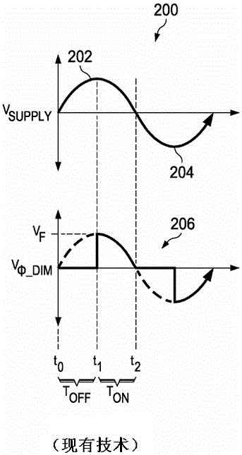
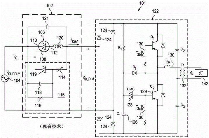
However, when a low power lamp such as a 6 watt LED bulb might be used, the current drawn by the lamp 142 may not be sufficient to sustain oscillations in the transformer 122, which can lead to unreliable effects such as visible flicker and less than indicated by the dimmer. level of total light output reduction
[0022] In addition, conventional methods cannot effectively detect or sense the type of transformer the lights are coupled to, further making it difficult to ensure compatibility between low power lights (e.g., less than 12 watts) and their coupling to the electrical infrastructure

Method used


Image

  • Systems and methods for controlling a power controller
  • Systems and methods for controlling a power controller
  • Systems and methods for controlling a power controller

Examples


Embodiment Construction

[0036] Figure 5 An embodiment in accordance with the present invention illustrates an example lighting system 500 that includes a controller 60 integrated into a lamp assembly 90 for providing compatibility between low power light sources (eg, LEDs 80 ) and other elements of the lighting system 500 . like Figure 5 As shown, a lighting system 500 may include a voltage source 5 , a leading edge dimmer 10 , an electronic transformer 20 , and a lamp assembly 90 . The voltage source 5 may generate a supply voltage such as a nominal 60Hz / 110V line voltage in the United States of America or a nominal 50Hz / 220V line voltage in Europe.

[0037] Leading edge dimmer 10 may include any system, device, or device for generating a dimming signal to other elements of lighting system 500, the dimming signal representing a dimming level that causes lighting system 500 to adjust the power delivered to lamp assembly 90, And thus, depending on the dimming level, the brightness of the LED 80 or...


PUM


Abstract

In accordance with systems and methods of the present disclosure, an apparatus may include a power converter and a controller. The controller may be configured to monitor a voltage at an input of the power converter, cause the power controller to transfer energy from the input to a load at a target current, decrease the target current responsive to determining that the voltage is less than or equal to an undervoltage threshold, and increase the target current responsive to determining that the voltage is greater than or equal to a maximum threshold voltage.

Description

[0001] related application [0002] This application claims priority to US Provisional Patent Application Serial No. 61 / 736,942, filed December 13, 2012, which is hereby incorporated by reference in its entirety. [0003] This application claims priority to US Provisional Patent Application Serial No. 61 / 756,744, filed January 25, 2013, which is hereby incorporated by reference in its entirety. [0004] This application claims priority to US Patent Application Serial No. 13 / 909,591, filed May 28, 2013, which is hereby incorporated by reference in its entirety. [0005] This application claims priority to US Patent Application Serial No. 13 / 909,632, filed May 28, 2013, which is hereby incorporated by reference in its entirety. technical field [0006] The present invention relates generally to the field of electronics, and more particularly, to systems and methods for ensuring compatibility between one or more low power lamps and the power inner structure to which they are cou...

Claims


Application Information

Patent Timeline
Patent Type & Authority Applications(China)
IPC IPC(8): H05B33/08H05B44/00
CPCF21V23/02H05B33/0815H05B33/0839H05B45/38H05B45/375H05B45/382
Inventor 埃里克·J·金丹尼尔·J·贝克约翰·L·梅安森
Owner SIGNIFY HLDG BV
Learn More