Microacoustic component and method for the production thereof

An acoustic and device technology, applied in the field of micro-acoustic devices, can solve problems such as hindering miniaturization and expensive technical measures

Active Publication Date: 2015-11-04
快速追踪有限公司
View PDF3 Cites 5 Cited by
  • Summary
  • Abstract
  • Description
  • Claims
  • Application Information

AI Technical Summary

Problems solved by technology

However, traditional overlays increase the price of manufacturing costs and / or hinder the continued trend of miniaturization
[0005] A further problem with microacoustic devices is that expensive technical measures are required to provide an optimal medium for the acoustic signal if high demands are placed on the signal quality

Method used


Image

  • Microacoustic component and method for the production thereof
  • Microacoustic component and method for the production thereof
  • Microacoustic component and method for the production thereof

Examples


Embodiment Construction

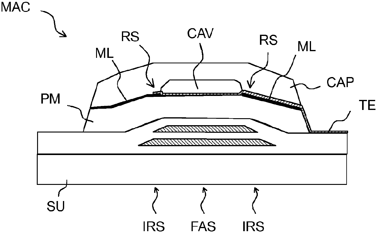
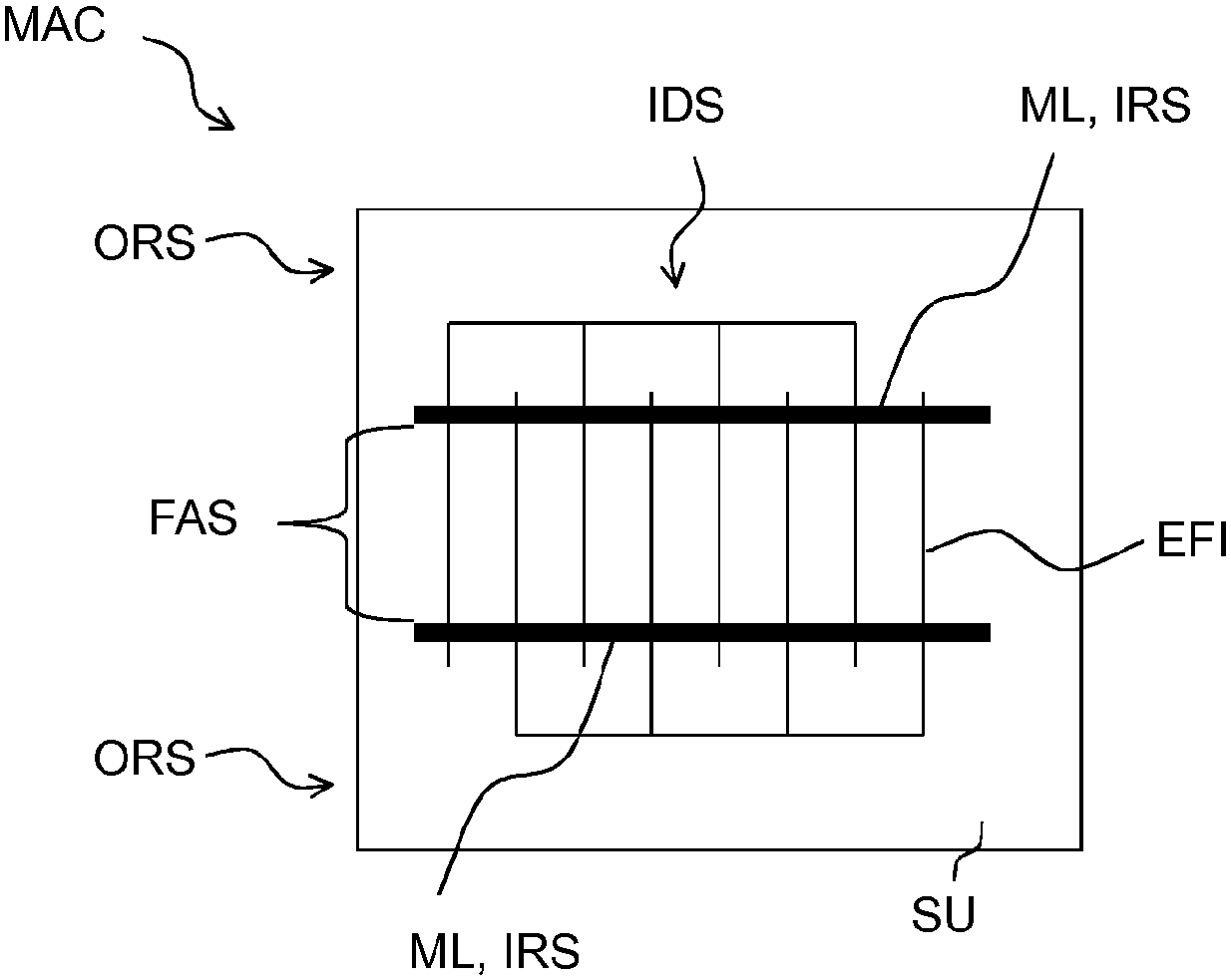
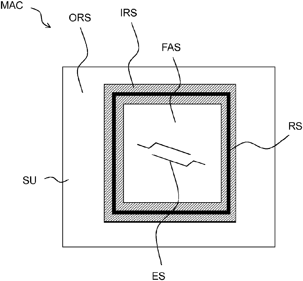
[0055] figure 1 The relationship between the acoustically functional area FHS, the inner edge area IRS and the outer edge area of ​​the micro-acoustic device MAC is shown. Sound waves can propagate in the acoustically functional area FAS. Ideally, here as little acoustic energy as possible is radiated into the remaining regions of the component. Thus, the outer edge region ORS and the acoustically functional region FAS are substantially acoustically decoupled. figure 1 The lower part shows the amplitude AMP of the acoustic wave in the device. Ideally, the amplitude is substantially constant in the acoustically functional region and zero in the outer edge region ORS. In the intervening transition region, the inner edge region IRS, the amplitude drops. figure 1 The upper part of shows the corresponding technical characteristics of the device. The covering CAP is arranged over the structure of the acoustically functional area. The support area of ​​the cover, ie the area wi...


PUM


Abstract

The invention relates to a microacoustic component (MAC) comprising a cover (CAP) which forms a hermetic seal and having improved acoustic properties, e.g. as a result of the positioning of the cover. The component comprises a functional acoustic region (FAS), an inner edge region (IRS) and an outer edge region (ORS). The cover (CAP) covers the functional acoustic region (FAS) and has a thin film and a contact surface (RS). The inner edge region (IRS) is acoustically coupled to the functional acoustic region (FAS) and the contact surface (RS) lies directly on at least one part of the inner edge region (IRS).

Description

technical field [0001] The invention relates to a microacoustic component, for example a component with an electroacoustic active region, the functional region being covered by a cover, and a method for producing such a component. Background technique [0002] Microacoustic components comprise functional regions in which sound waves can propagate. Such devices may for example comprise electroacoustic transducers with electrode structures and piezoelectric materials and utilize SAW (SAW = Surface Acoustic Wave = Surface Acoustic Wave), BAW (BAW = Bulk Acoustic Wave = Bulk Acoustic Wave) or GBAW (GBAW = Guided Bulk Acoustic Wave) Acoustic Wave = guided body acoustic wave) to work. Such components may be HF filters and are used, for example, in mobile communication devices. [0003] The characteristic magnitude of an RF filter operating with sound waves is essentially given by the propagation speed and frequency of the sound waves in the concentrated material. A characterist...

Claims


Application Information

Patent Timeline
IPC IPC(8): H03H9/10H03H9/02H03H3/02H03H3/08H03H9/05
CPCH03H3/02H03H3/08H03H9/02118H03H9/02858H03H9/0542H03H9/105H03H9/1092H10N30/081H10N30/082H03H9/02007H03H9/02086H03H9/02818H03H9/02984H03H9/14544H03H9/25
Inventor G.亨B.巴德
Owner 快速追踪有限公司
Why Eureka
Try Eureka