Propulsion device for ship

A technology for ships and propulsion devices, applied in the field of ship propulsion devices, can solve the problems of difficulty in absorbing rotating components, no propulsion devices are provided, and no descriptions, etc., to achieve the effects of improving propulsion efficiency, improving ship operation performance, and improving thrust

Active Publication Date: 2015-11-04
SAMSUNG HEAVY IND CO LTD
View PDF10 Cites 5 Cited by
  • Summary
  • Abstract
  • Description
  • Claims
  • Application Information

AI Technical Summary

Problems solved by technology

While the above prior art documents achieve precise maneuverability and efficient traction, they do not provide an adequate description of the development of propulsion devices that provide higher propulsion efficiencies
[0010] In addition, the prior art only mentions outward flare and open angle, where the leading edge direction of the open angle is widened, without describing any technique for reducing the vortex generated by the propeller
Therefore, it may be difficult to absorb the rotational component of a propeller started in bollard conditions where only the propeller is rotating at the rated RPM when the vessel or vessel structure is nearly stationary

Method used


Image

  • Propulsion device for ship
  • Propulsion device for ship
  • Propulsion device for ship

Examples


Embodiment Construction

[0039] Embodiments of the present invention will be specifically described below with reference to the accompanying drawings. In the following description, when it is determined that a specific description of a related known function or configuration unnecessarily obscures the gist of the present invention, the detailed description will be omitted.

[0040] A comparative example for an embodiment of the present disclosure employs a standard airfoil, which is a ship type 19A airfoil (hereinafter referred to as comparison example).

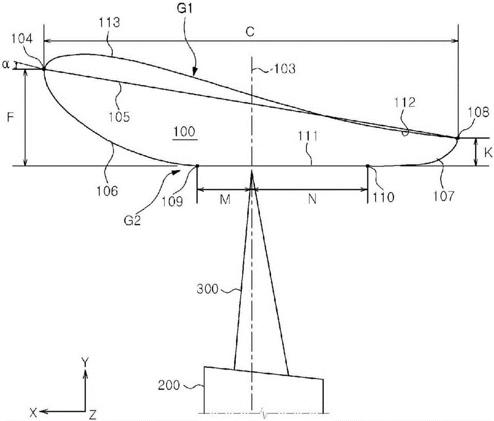
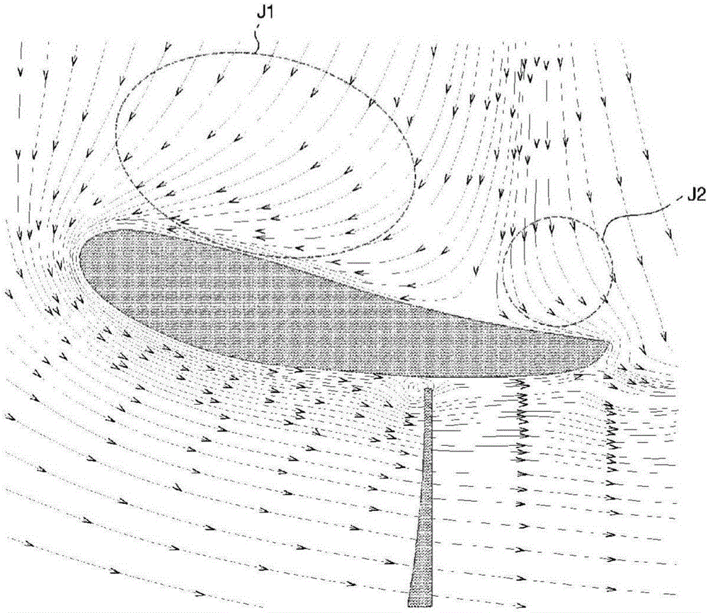
[0041] figure 1 shows an exemplary catheter of a propulsion device according to a first embodiment of the present disclosure, while figure 2 show figure 1 Streamline distribution obtained by 2D CFD (Computational Fluid Dynamics) of the catheter shown.

[0042] refer to figure 1, the propulsion device according to the first embodiment includes a hub 200, a propeller 300 and an annular duct 100, wherein the hub 200 receives power through a rotat...


PUM


Abstract

A propulsion device for a ship is introduced. The propulsion device for the ship comprises a duct having a nose corresponding to the front vertex of a hydrofoil cross-section and a tail corresponding to the rear vertex of the hydrofoil cross-section, wherein the shape of the duct cross-section comprises: an outer surface formed upward in a convex shape at the front end of the duct and formed downward in a concave shape at the rear end of the duct; an inner front part of the duct formed downward in a convex shape at the front end of the duct; an inner rear part of the duct formed downward in a convex shape at the rear end of the duct; and a parallel part for connecting the inner forward part and the inner backward part in parallel to each other.

Description

technical field [0001] The present disclosure relates to a marine propulsion device, and more particularly, to a marine propulsion device capable of reducing vortices left around a hub by utilizing blades of different sizes having a duct section adapted to the characteristics of the flow within the duct. Background technique [0002] Increasing concerns about the maneuverability and propulsion efficiency of ships has led to an increasing interest in the main and auxiliary propulsion units provided in ships. For example, vessels such as drill ships are equipped with azimuth thrusters used to generate thrust for precise positioning or to tow other vessels during high or low speed voyages. [0003] There are two variants of azimuth thrusters based on the application, namely: open azimuth thrusters without ducts (such as propellers); and ducted azimuth thrusters with ducts, wherein the ducts have wings surrounding the ducted azimuth thrusters type section. [0004] The above-m...

Claims


Application Information

Patent Timeline
Patent Type & Authority Applications(China)
IPC IPC(8): B63H5/15B63H1/28
CPCB63H5/15B63B35/66B63H2001/283B63H2005/1254B63B35/68B63H5/08B63H5/10B63H5/125B63H5/14B63H2005/103
Inventor 宋志修卢载彧吴世勉李东炫郑载权朴光根朴烔吉白光俊李政勳李振奭李泰九
Owner SAMSUNG HEAVY IND CO LTD
Why Eureka
Try Eureka