Rebar Anchored Connection Structure and Connection Method of Prefabricated Concrete Members

A prefabricated concrete and steel bar anchoring technology, applied to structural elements, building components, manufacturing tools, etc., can solve the problems of increased overlapping length of steel bars, increased amount of grouting materials, random construction operations, etc., to achieve small size and enhanced bonding Good performance and connection effect

Inactive Publication Date: 2018-07-03
CHANGAN UNIV
View PDF6 Cites 0 Cited by
  • Summary
  • Abstract
  • Description
  • Claims
  • Application Information

AI Technical Summary

Problems solved by technology

However, the existing reserved holes for anchorage of steel bars are reserved holes with smooth inner walls, and the bonding effect between the holes and the pouring mortar is poor, which increases the overlapping length of steel bars and increases the amount of grouting materials, resulting in poor economic benefits.
In addition, at present, there is no unified, standardized and specific construction method to follow when connecting prefabricated concrete structures. In actual construction, it is inevitable that the construction operations are relatively random, irregular, cumbersome, and the construction workers are low. Problems such as poor connection quality

Method used


Image

  • Rebar Anchored Connection Structure and Connection Method of Prefabricated Concrete Members
  • Rebar Anchored Connection Structure and Connection Method of Prefabricated Concrete Members
  • Rebar Anchored Connection Structure and Connection Method of Prefabricated Concrete Members

Examples


Embodiment 1

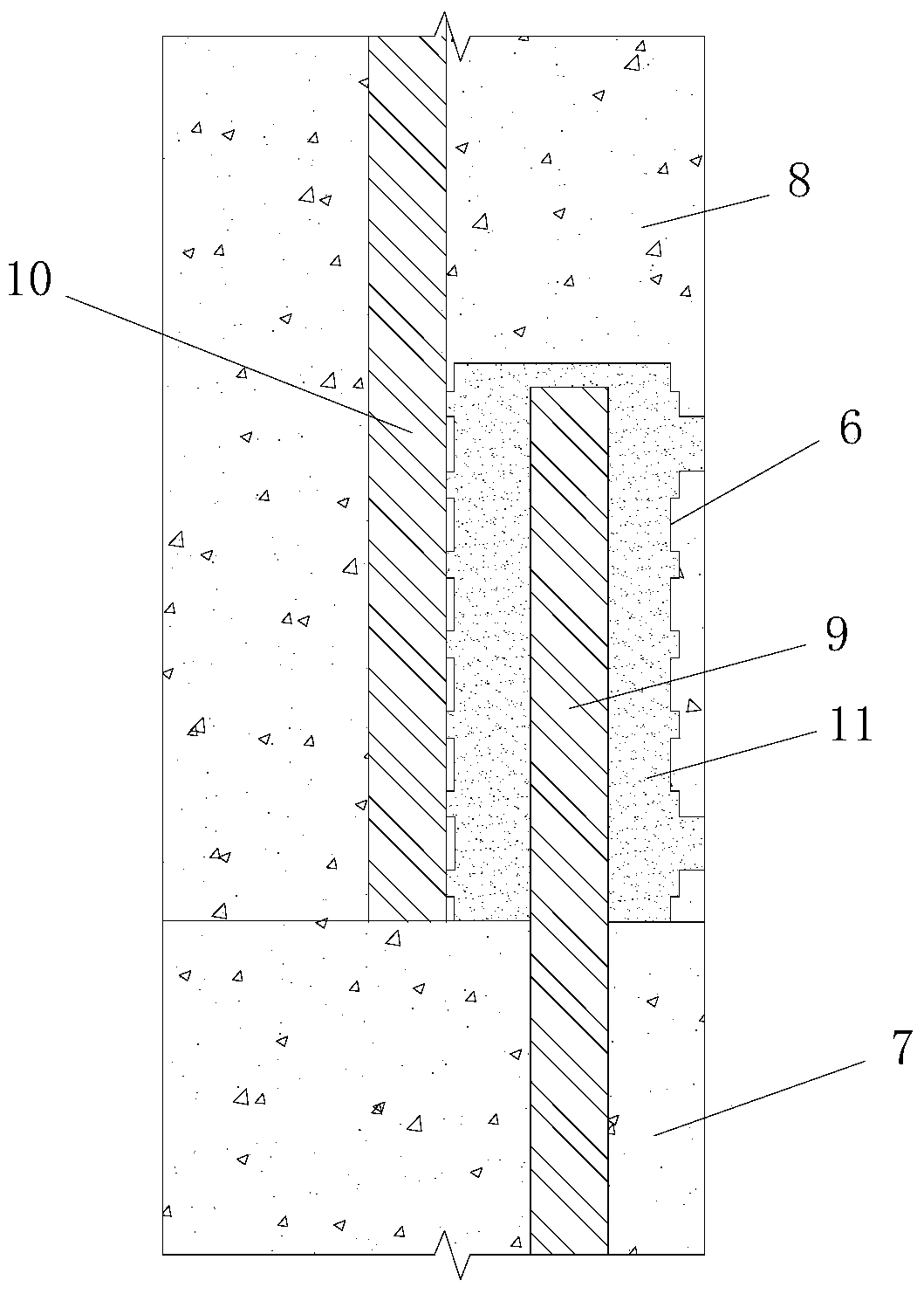
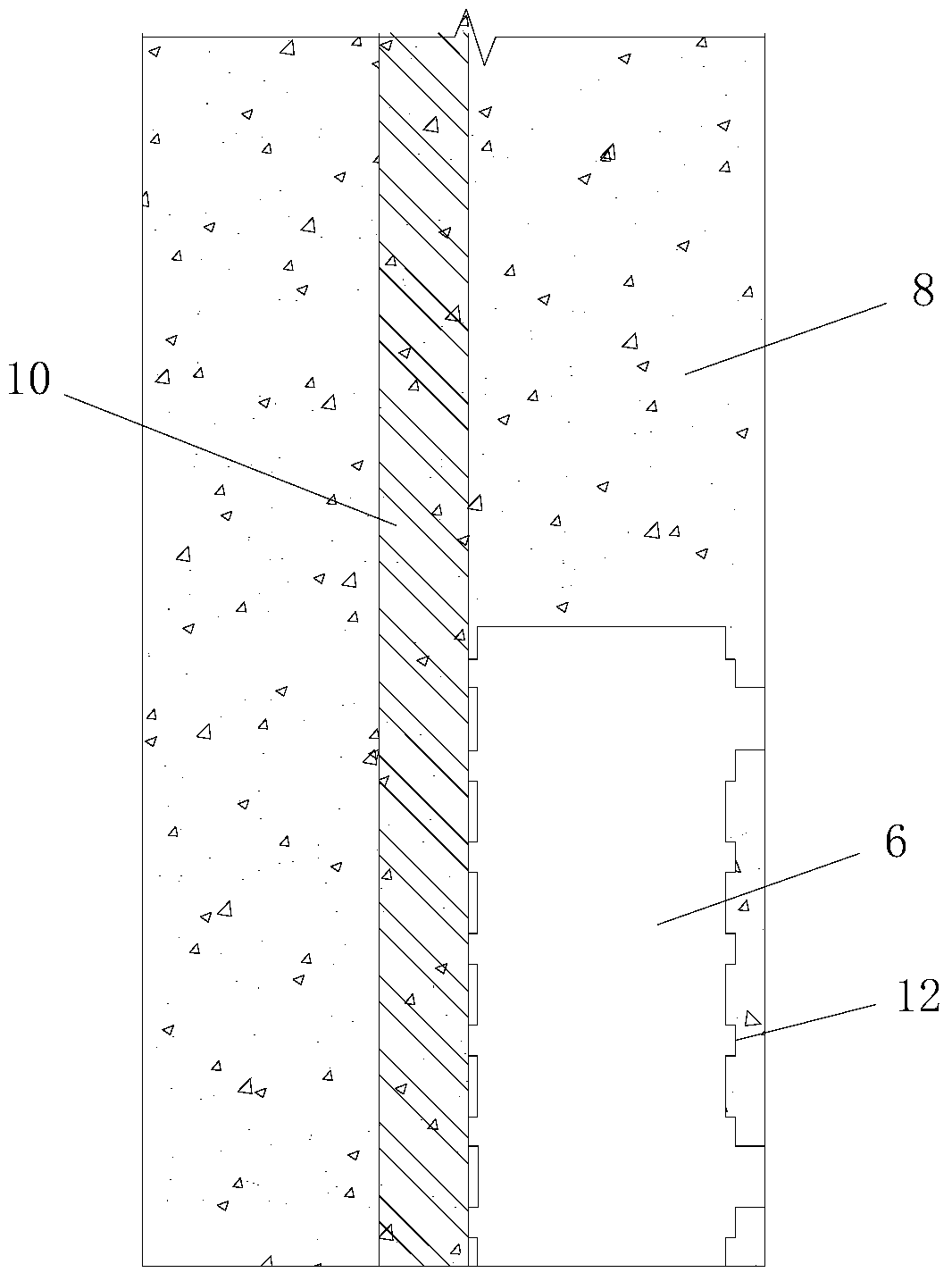
[0052] Such as figure 1 The illustrated prefabricated concrete component anchorage connection structure includes a first prefabricated concrete component 7 and a second prefabricated concrete component 8 above the first prefabricated concrete component 7; figure 2 , the bottom of the second prefabricated concrete member 8 is provided with a steel bar anchoring reserved hole 6 for anchoring the first steel bar 9, and the first steel bar 9 is a pre-embedded steel bar embedded in the first prefabricated concrete member 7 and its The upper end protrudes to the outside of the first precast concrete member 7, and the upper end of the first steel bar 9 is inserted into the reserved hole 6 for anchoring the steel bar from bottom to top. A grouting structure 11 formed by grouting material is provided in the cavity between the steel bar anchoring reserved hole 6 and the first steel bar 9, and the first steel bar 9 is fastened and fixed to the steel bar anchoring reserved hole through t...

Embodiment 2

[0090] In this example, if Figure 7 As shown, the difference between the steel bar anchoring connection structure used and the embodiment 1 is that: the steel bar anchoring reserved hole 6 is provided with a spiral bar 13 , and the spiral bar 13 is coaxially sleeved on the first steel bar 9 .

[0091] In this embodiment, the structure of the remaining part of the steel bar anchorage connection structure is the same as that in Embodiment 1.

[0092] In this example, if Figure 8 As shown, the steel bar anchoring connection method adopted is different from that of Example 1 in that: before the second prefabricated concrete member is hoisted and the first steel bar is inserted in step 2, the spiral bar 13 is first set on the first steel bar 9; The hoisting equipment lifts the second precast concrete member 8 above the first precast concrete member 7, and lowers the second precast concrete member 8, so that the first steel bar 9 and the spiral bar 13 set outside it are inserted ...


PUM

PropertyMeasurementUnit
diameteraaaaaaaaaa
heightaaaaaaaaaa
compressive strengthaaaaaaaaaa

Abstract

The invention discloses a steel bar anchor connection structure and connection method of prefabricated assembled concrete components. The steel bar anchor connection structure comprises a first prefabricated concrete component and a second prefabricated concrete component located above the first prefabricated concrete component. The bottom of the component is provided with a steel bar anchoring reserved hole for anchoring the first steel bar embedded in the first prefabricated concrete member; a grouting structure is provided in the cavity between the steel bar anchoring reserved hole and the first steel bar; the steel bar anchoring reserved The hole is located outside the lower part of the second steel bar arranged in the second prefabricated concrete member, and a plurality of grooves are arranged on the inner side wall of the reserved hole for anchoring the steel bar; the method for anchoring and connecting the steel bar includes the steps: 1. Prefabrication of the second prefabricated concrete member; 2. 1. Hoisting of the second precast concrete component and insertion of the first steel bar; 3. Grouting; 4. Maintenance. The invention is reasonable in design, convenient in realization and good in use effect, can simply and quickly complete the steel bar connection process and is reliable in connection.

Description

technical field [0001] The invention belongs to the technical field of construction of prefabricated assembled concrete components, and in particular relates to a reinforcement anchorage connection structure and connection method of prefabricated assembled concrete components. Background technique [0002] The development of construction industrialization is the fundamental transformation of the construction production mode from extensive production to intensive production, and it is the inevitable way and development direction of industrial modernization. The use of prefabricated concrete structures is an effective way to realize the industrialization of buildings. It is a concrete structure made of prefabricated concrete components as the main component, which is assembled, connected and partially cast in place. Foreign concrete prefabricated components and reinforced concrete started almost at the same time, but industrialized prefabricated concrete components in the mode...

Claims


Application Information

Patent Timeline
Patent Type & Authority Patents(China)
IPC IPC(8): E04B1/41E04C5/16B28B23/02B28B7/16
Inventor 吴涛刘喜陈旭邢国华刘伯权
Owner CHANGAN UNIV
Why Eureka
Try Eureka