
Cylindrical oil drum carrying device

A technology for handling devices and oil drums, which is applied in the direction of transportation and packaging, manual conveying devices, etc., can solve the problems of unstable positioning of oil drums, large volume of transport vehicles, and insufficient mobility and flexibility, and achieve fast and convenient clamping, small size, The effect of simple overall structure

Inactive Publication Date: 2015-11-04
ZHEJIANG GEELY AUTOMOBILE +2
View PDF9 Cites 8 Cited by
  • Summary
  • Abstract
  • Description
  • Claims
  • Application Information

AI Technical Summary

Problems solved by technology

Its disadvantage is that this kind of oil drum truck is large in size, not flexible enough, the positioning of the oil drum is unstable during the handling process, and it is easy to cause the danger of slipping, and the oil drum is easy to tilt during the handling process.

Method used


Image

  • Cylindrical oil drum carrying device
  • Cylindrical oil drum carrying device
  • Cylindrical oil drum carrying device

Examples


Embodiment Construction

[0027] The present invention will be further described below in conjunction with accompanying drawing and specific embodiment:

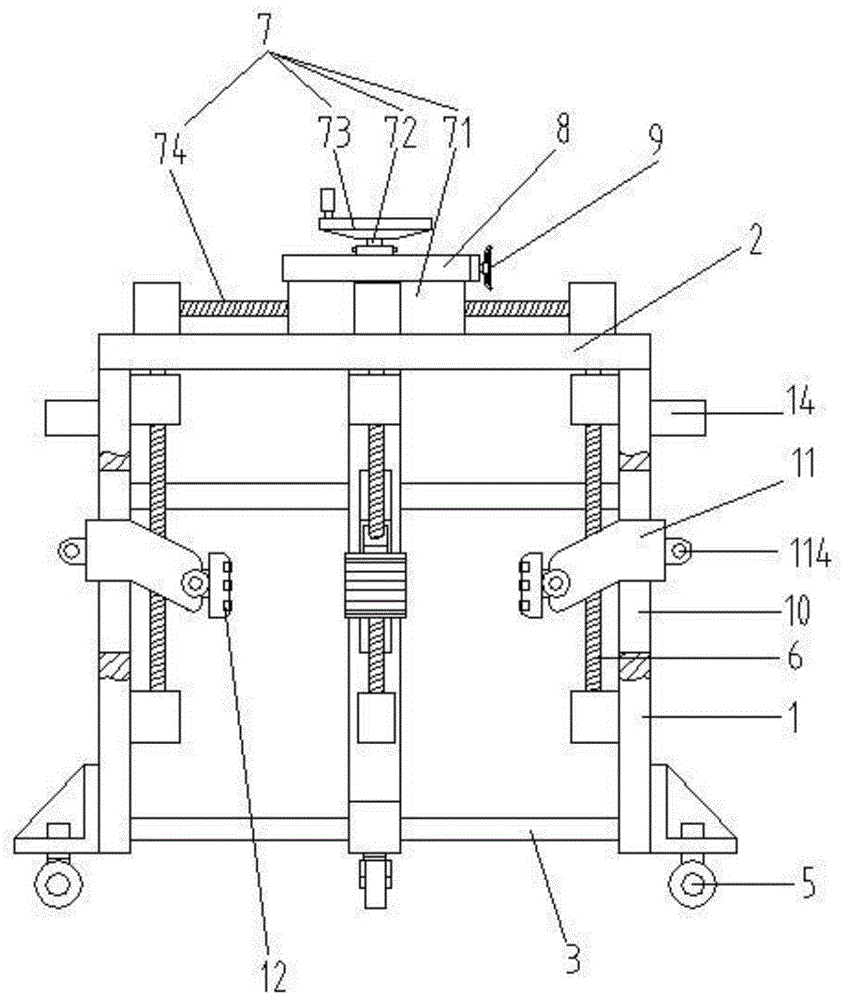
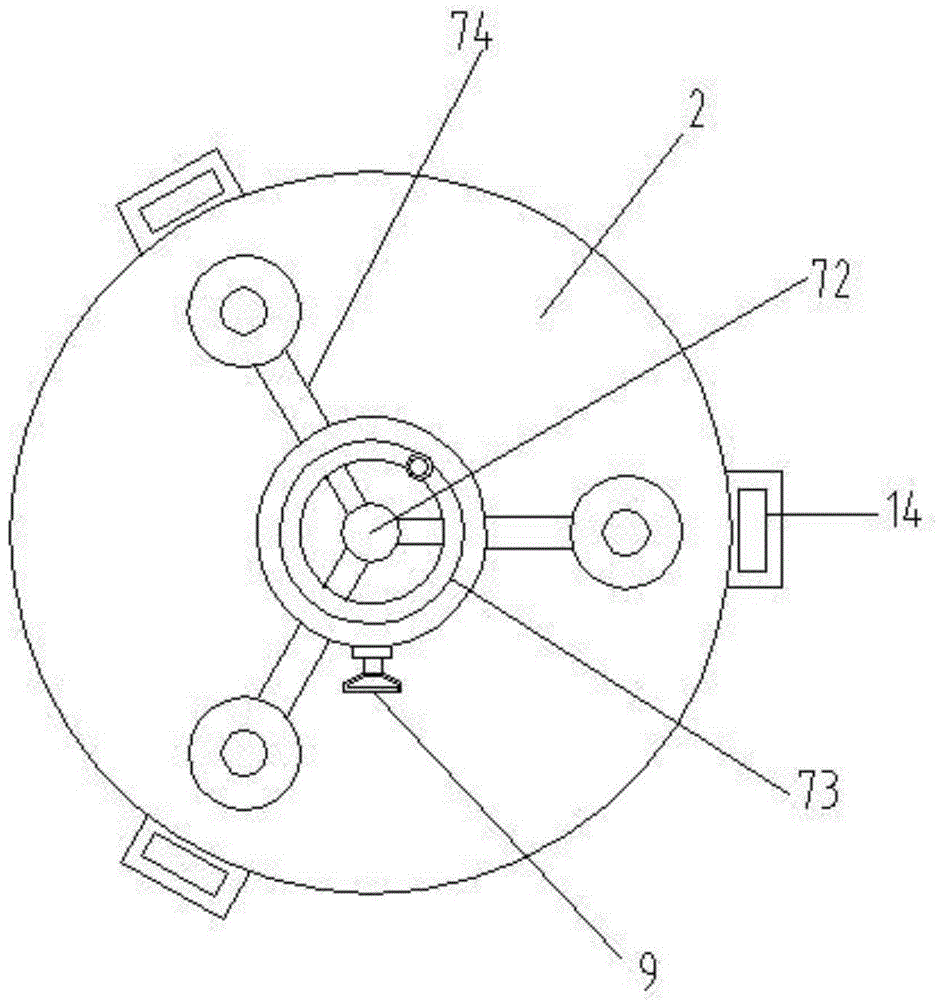
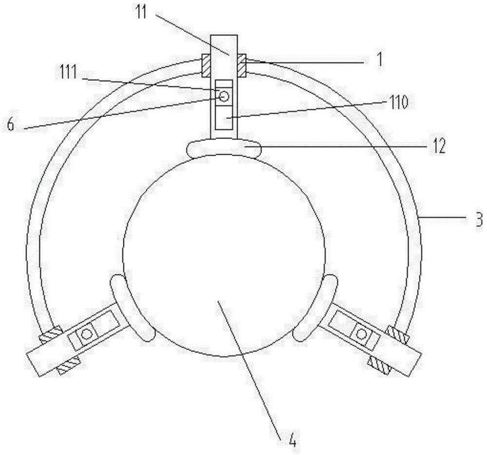
[0028] Such as figure 1 A columnar oil drum handling device shown includes three uprights 1 and a base plate 2 connecting the uprights. The base plate 2 is a horizontal circular plate, and the uprights 1 are vertically fixed at the edge of the lower side of the base plate, and there are connecting rods between the uprights. 3. There is no connecting rod installed between the two uprights, so that it can be directly inserted into the oil drum 4 from the side. When the diameter of the oil drum is large, it can also be directly covered from the top of the oil drum. There is a handle 14 on the outside of the upright 1 The lower end of the column 1 is provided with a bottom wheel 5, and the inner surface of each column is provided with a parallel lifting screw 6, and the upper side of the base plate 2 is used to drive a screw drive mechanism 7 for synchro...


PUM


Abstract

The invention relates to the technical field of oil drum carrying and particularly discloses a cylindrical oil drum carrying device. The cylindrical oil drum carrying device comprises three uprights and a base board for connecting the uprights. The base board is a horizontal circular board. The uprights are perpendicularly fixed to the edge of the lower side face of the base board. Connecting rods are arranged between the uprights. Bottom wheels are arranged at the lower ends of the uprights. The inner side faces of the uprights are provided with parallel lifting screws. A screw driving mechanism used for driving the lifting screws to rotate synchronously is arranged on the upper side face of the base board. Vertical guide grooves penetrating the inner sides and the outer sides of the uprights are arranged on the uprights. Clamping seats are arranged in the guide grooves. The outer ends of the clamping seats extend into the guide grooves. Clamping blocks are arranged at the inner ends of the clamping seats. Chutes inclining from the outer ends to the inner ends downwards are arranged in the clamping seats. Sliding blocks are arranged in the chutes. The lifting screws penetrate the sliding blocks and are in threaded connection with the sliding blocks. Therefore, the cylindrical oil drum carrying device has the beneficial effects of being simple in structure, small in size, stable in carrying and convenient to use.

Description

technical field [0001] The invention relates to the technical field of oil barrel handling, in particular to a columnar oil barrel handling device. Background technique [0002] In the manufacturing industry, it is often necessary to use a large amount of liquid auxiliary oil, such as drawing oil, lubricating oil, engine oil, etc. These auxiliary oils are generally stored in large iron drums or plastic drums, and these large oil drums are generally columnar structure, and the weight is relatively large, there is generally no handle on the oil drum, the workload of manual handling is large, and the handling efficiency is low; now, hydraulic vehicles are usually used for handling, and the upper edge of the oil drum is clamped by the chuck on the hydraulic vehicle, and then passed The hydraulic cylinder rises to make the oil barrel leave the ground, and then realizes handling and transfer. However, the hydraulic vehicle is large in size and high in cost, and cannot pass through...

Claims


Application Information

Patent Timeline
IPC IPC(8): B65G7/02
Inventor 朱立赞邓林青安聪慧冯擎峰
Owner ZHEJIANG GEELY AUTOMOBILE
Learn More