Method for breaking ice based on reducing supporting force of ice layer, and ice breaking ship

A support force and icebreaker technology, applied to icebreakers and other directions, can solve the problems of high tonnage requirements and high energy consumption of icebreakers, and achieve the effect of improving icebreaking efficiency

Inactive Publication Date: 2015-11-04
付文军
View PDF5 Cites 2 Cited by
  • Summary
  • Abstract
  • Description
  • Claims
  • Application Information

AI Technical Summary

Problems solved by technology

[0005] In view of the above analysis, the current "head-to-head" technical thinking for icebreaking has the limitations of requiring high tonnage of icebreakers and consuming a lot of energy

Method used


Image

  • Method for breaking ice based on reducing supporting force of ice layer, and ice breaking ship
  • Method for breaking ice based on reducing supporting force of ice layer, and ice breaking ship

Examples


Embodiment 1

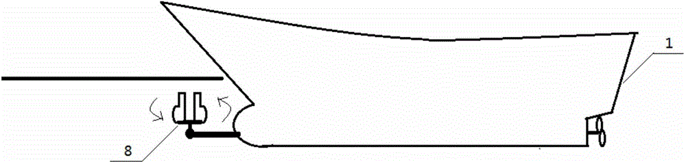
[0020] like figure 1 As shown, the vortex-manufacturing icebreaker of the present invention includes an icebreaker 1 and a rotator 8. The rotator 8 is fixedly installed on the front lower part of the hull of the icebreaker 1 and is connected with the rotary drive system in the ship. The rotating part of the rotator is a bottom double A spoon-shaped tuning fork. When it is necessary to start the rotator to break the ice, the rotation of the rotator will create a vortex under the ice layer in front of the bow. The huge downward attraction of the vortex will reduce the local support force of the ice layer a lot, and the huge weight of the ice layer in this part will appear. Collapse tends to fracture the ice even under enormous downward stress.

Embodiment 2

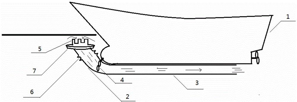
[0022] like figure 2 Shown is the tubular type diversion device type icebreaker of the present invention, the fence nozzle 5 of tubular diversion device 2 is the water inlet when working, and its diameter is 2 meters, is designed with a gap, and the depth of the gap is 1.2 meters, mainly to prevent diversion. The negative pressure generated during the flow process and the buoyancy of the floating ring 7 cause the water inlet to stick to the ice layer and hinder the flow diversion. The function of the floating ring 7 is to keep the water inlet and the ice layer at an appropriate distance to ensure the best negative pressure. The design of the telescopic tube part 6 is mainly to be able to move properly when the ice layer breaks, so as to prevent the tube type flow guiding device 2 from being damaged. When the pump 4 in the fixed pipe part 3 is started, the water under the ice layer will quickly enter the pipe-type deflector 2 and flow out to the stern through the pipe. Water ...


PUM


Abstract

The invention discloses a method for breaking ice based on reducing the supporting force of an ice layer, and an ice breaking ship, and relates to the technical field of the manufacturing of ice breaking ships. The method is characterized in that below an ice surface at an ice breaking position, a water pump is adopted to guide flow downwards or rotating machinery is adopted to make vortexes, so that negative pressure is generated, and the supporting force of the ice surface is reduced; the method is matched with the ice breaking ship for breaking ice. According to the method, ice is broken from the foundation, so that the weight of the ice layer becomes the weakness of the ice layer, and the degree of difficulty of breaking ice is greatly lowered. Through the adoption of the new ice breaking method, an ice breaking ship of small tonnage is enabled to break thick ice in extremely cold areas, so that the ice breaking method has an extremely extensive application prospect.

Description

technical field [0001] The invention relates to the technical field of icebreaker manufacture, in particular to a new icebreaking method and icebreaking device, which can greatly reduce the difficulty of icebreaking for icebreakers, and especially provide the possibility for small tonnage icebreakers to break through thick ice. Background technique [0002] Today's icebreakers rely on super-large tonnage and powerful power to cut through the ice head-on, and adjust the weight of the front and rear cabins to crush the ice to break the ice, which is indeed effective. However, the traditional method faces the problem that breaking thick ice must be supported by a large-tonnage ship and huge power, and the ice-breaking speed is slow. For example, the Antarctic icebreaker Xuelong encountered ice more than 1 meter thick this year and had to wait for changes in wind direction and weather to get out of trouble. This fully demonstrates that at present, large-tonnage icebreakers can b...

Claims


Application Information

Patent Timeline
IPC IPC(8): B63B35/08
Inventor 付文军
Owner 付文军
Why Eureka
Try Eureka