High-speed connecting-rod press with integrated strut

A technology of integral pillars and presses, applied in the direction of presses, manufacturing tools, etc., can solve the problems of pillar deformation, complex dimensional chain, and incorrect position of supporting beams, etc., and achieve the effect of reducing installation difficulty and reducing accumulation

Inactive Publication Date: 2015-11-04
TIANJIN TIANDUAN PRESS CO LTD
View PDF6 Cites 0 Cited by
  • Summary
  • Abstract
  • Description
  • Claims
  • Application Information

AI Technical Summary

Problems solved by technology

[0002] At present, in the high-speed connecting rod press, because the balance cylinder or partial load cylinder is installed on the support beam, the position of the support beam needs to be accurate, and because the front pillar and the rear pillar are respectively connected with the upper beam and the lower beam In order to ensure that the supporting beam can be placed in the middle of the front and rear pillars, a grinding plate is added during the installation process, which makes the dimensional chain of the whole part too complicated, requiring high machining accuracy and increasing the installation The complexity of the process; in addition, due to the stability of the pressure rod, the pre-tightening of the tie rod deforms the pillar, which causes the lateral deformation of the pillar where the support beam is installed, causing the position of the support beam to be incorrect

Method used


Image

  • High-speed connecting-rod press with integrated strut
  • High-speed connecting-rod press with integrated strut

Examples


Embodiment Construction

[0013] In order to further understand the invention content, characteristics and effects of the present invention, the following examples are given hereby, and the details are as follows:

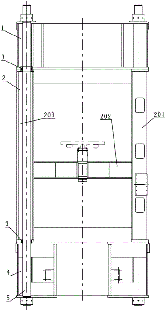
[0014] Such as figure 1 as shown,

[0015] A high-speed connecting rod press with an integral pillar, including an upper beam 1, a lower beam 4, and an integral pillar. The integral pillar is composed of two front pillars 201, two rear pillars 203, and a supporting beam 202. The supporting beam is welded Connect the front pillar and the rear pillar, the pillar is equipped with a tie rod 5, between the front pillar and the upper beam, between the front pillar and the lower beam, between the rear pillar and the upper beam, and between the rear pillar and the lower beam. The ring is positioned by the positioning ring 3.

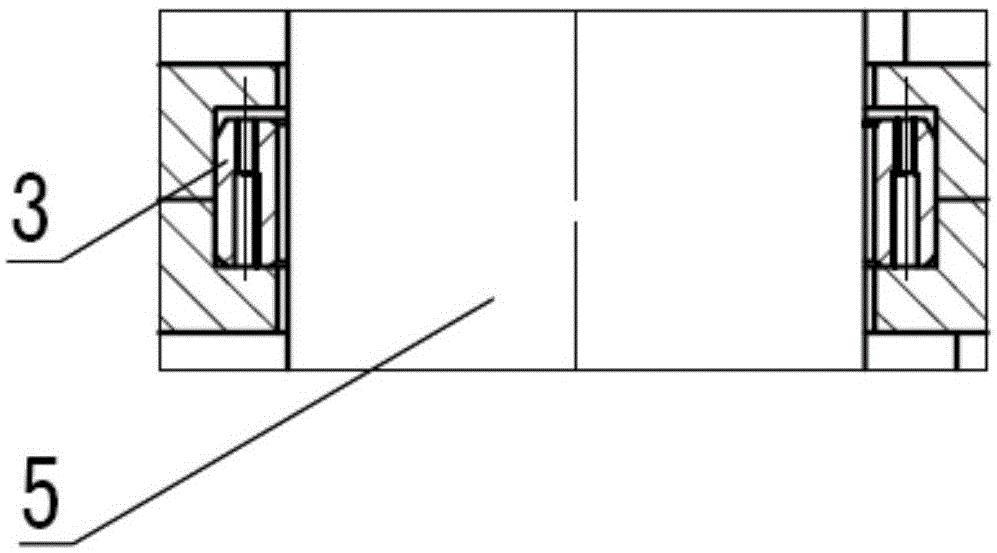
[0016] Such as figure 2 As shown, the positioning ring is responsible for the positioning between the upper and lower beams and the front and rear pillars, wherein the up...


PUM


Abstract

The invention relates to a high-speed connecting-rod press with an integrated strut. The high-speed connecting-rod press comprises an upper crossbeam and a lower crossbeam and is characterized in that the high-speed connecting-rod press further comprises the integrated strut, and the integrated strut is composed of two front strut bodies, two rear strut bodies and supporting crossbeams; the supporting crossbeams are used for connecting the front strut bodies with the rear strut bodies in a welding mode, and pulling rods penetrate through the strut; locating rings are arranged between the front strut bodies and the upper crossbeam, between the rear strut bodies and the upper crossbeam, between the front strut bodies and the lower crossbeam and between the rear strut bodies and the lower crossbeam, and the front strut bodies, the rear strut bodies, the upper crossbeam and the lower crossbeam are located through the locating rings. The high-speed connecting-rod press has the advantages that the requirement for optimizing the equipment installation process is met, and meanwhile the requirement for optimizing producing and machining links of equipment products is met.

Description

technical field [0001] The invention belongs to the technical field of high-speed connecting rod presses, and in particular relates to a high-speed connecting rod press with integral pillars. Background technique [0002] At present, in high-speed connecting rod presses, due to the balance cylinder or partial load cylinder installed on the support beam, the position of the support beam needs to be accurate. In order to ensure that the supporting beam can be better placed in the middle of the front and rear pillars, a grinding plate is added during the installation process, which makes the dimensional chain of the whole part too complicated, requiring high machining accuracy and increasing the installation The complexity of the process; in addition, due to the stability of the pressure rod, the pre-tightening of the tie rod deforms the pillar, which causes lateral deformation of the pillar where the support beam is installed, causing the position of the support beam to be inc...

Claims


Application Information

Patent Timeline
IPC IPC(8): B30B15/04
Inventor 魏明吕国胜
Owner TIANJIN TIANDUAN PRESS CO LTD
Why Eureka
Try Eureka