Method for controlling the injection process of an electromagnetic injector

一种电磁喷射器、喷射过程的技术,应用在电气控制、电磁体、发动机控制等方向,能够解决流体变化、电枢精确的打开时刻和关闭时刻很难确定等问题,达到提高精确性、燃烧特性好、喷射量控制精确的效果

Active Publication Date: 2018-10-12
ROBERT BOSCH GMBH
View PDF8 Cites 0 Cited by
  • Summary
  • Abstract
  • Description
  • Claims
  • Application Information

AI Technical Summary

Problems solved by technology

The precise opening and closing moments of the armature are difficult to determine here
These delay times may cause changes in the amount of fluid flowing through the electromagnetic injector

Method used


Image

  • Method for controlling the injection process of an electromagnetic injector
  • Method for controlling the injection process of an electromagnetic injector
  • Method for controlling the injection process of an electromagnetic injector

Examples


Embodiment Construction

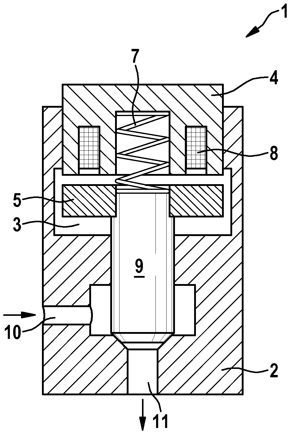
[0039] exist figure 1 An example of a non-current-closed (NC) electromagnetic injector 1 is shown in . The electromagnetic injector 1 has a valve body 2 in which an armature chamber 3 is formed. An armature 5 is arranged in this armature chamber 3 . Furthermore, a valve spring 7 is arranged in the armature chamber 3 . Furthermore, electromagnetic injector 1 has a solenoid coil 8 which surrounds valve spring 7 in an annular manner. The magnetic loop 4 serves as a yoke. A sealing element, here in the form of an injector needle 9 , is connected to the armature 5 . The electromagnetic injector 1 is equipped with an inflow port 10 and an outflow port 11 , but the directions described therein are merely exemplary directions.

[0040] So-called energization of the electromagnetic injector 1 takes place if an electric current is supplied to the electromagnetic coil 8 via an electrical line (not shown). As a result, a magnetic field is formed in the solenoid coil 8 , which causes...


PUM


Abstract

The invention relates to a method for controlling the injection process of an electromagnetic injector of an internal combustion engine, wherein the electromagnetic injector has a coil to which a first current (Ipre process, Imax, Isuction), short-circuit the coil in order to keep the electromagnetic injector open, and apply a second current (IS) to the coil in order to close the electromagnetic injector, wherein the second The current (IS) is in the opposite direction to said first current (Ipreconditioning, Imax, Iattraction).

Description

technical field [0001] The invention relates to a method for controlling the injection process of an electromagnetic injector. Background technique [0002] Electromagnetic injectors or solenoid injectors are known and used in many ways. Common electromagnetic injectors include a sealing element (also known as a valve needle or injector needle) that cooperates with a valve seat and can release and block the flow path of fluid. The sealing element is actuated electromagnetically. For this purpose, the electromagnetic injector comprises an armature, which is coupled to the sealing element. The armature and thus the sealing element are pressed by the valve spring into a current-free end position (“normal position”, “zero position”). In this end position, the flow path of the fluid is either blocked (NC) or opened (NO). [0003] By energizing the solenoid coil (so-called actuation), for example by means of so-called main energization or main actuation, an electromagnetic for...

Claims


Application Information

Patent Timeline
Patent Type & Authority Patents(China)
IPC IPC(8): H01F7/18
CPCF02D41/20H01F7/1805H01F7/1811F02D2041/2055F02M51/061F02D2041/2003F02D2041/2058F02D41/3005
Inventor J.屈纳B.施图克P.伯兰德W.富克斯F.兰德霍伊泽O.奥尔哈费尔V.特里奇
Owner ROBERT BOSCH GMBH
Why Eureka
Try Eureka