vertical axis wind turbine

A wind energy and axis technology, applied in the field of vertical axis wind turbines, can solve problems such as wind flow can not be

Active Publication Date: 2018-11-02
PANIPA
View PDF4 Cites 0 Cited by
  • Summary
  • Abstract
  • Description
  • Claims
  • Application Information

AI Technical Summary

Problems solved by technology

Therefore, it is not possible to arrange multiple wind turbines so close to each other that the wind flow blocked by one wind turbine cannot be used to drive the rotor of another wind turbine in rotation
[0006] Furthermore, the time frame in which such wind turbines can be used is limited to approximately 2800 hours

Method used


Image

  • vertical axis wind turbine
  • vertical axis wind turbine
  • vertical axis wind turbine

Examples


Embodiment Construction

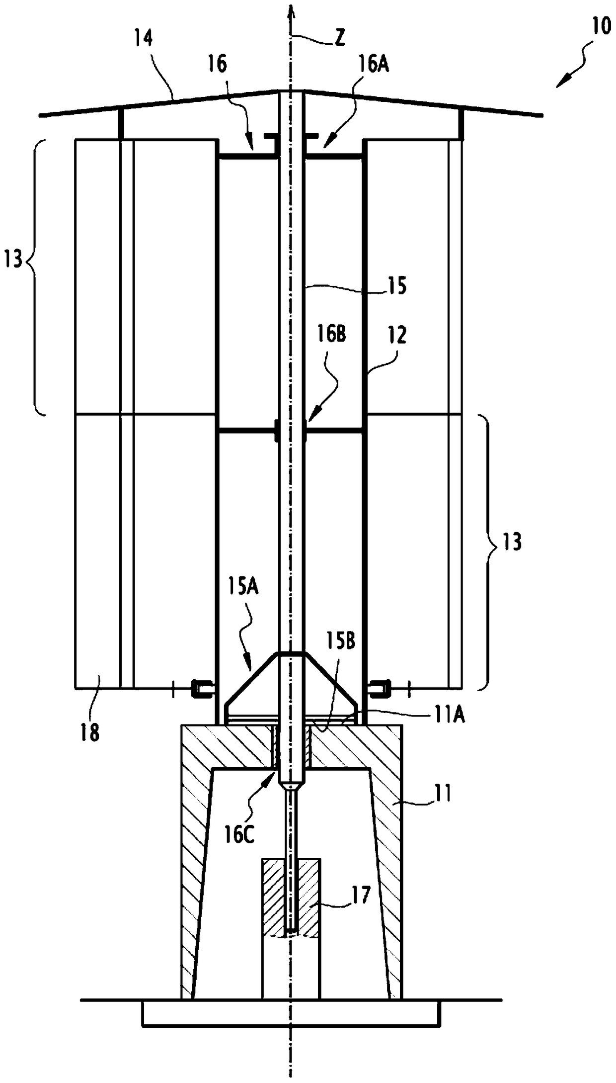
[0042] figure 1 A device 10 for converting wind energy into another type of energy is shown. In the example described, the other type of energy is electrical energy. Alternatively, however, another type of energy here may also be mechanical energy.

[0043] The energy conversion device 10 comprises a base 11 , and a hollow mast 12 mounted on the base 11 and extending along a substantially vertical axis Z.

[0044] According to the example described, a mast 12 is fastened to the structure 11 . The mast 12 is made, for example, of steel, and one or more parts thereof are then attached to the base 11 . Optionally, the mast 12 can be formed by pouring concrete directly on the base 11 using climbing formwork.

[0045] According to another alternative, the mast 12 can be mounted rotatably about a vertical axis Z relative to the base 11 , the reason for this will be explained later.

[0046] The energy conversion device 10 comprises at least one module 13 having a substantially ...


PUM


Abstract

The device (10) according to the invention comprises a base (11), a hollow mast (12) mounted on the base (11) and extending along a vertical axis (Z), and at least one rotatable around the mast (12) module (13). Said module (13) comprises at least one flap (18) movable about a pivot link (26) between a retracted position and a deployed position, and according to said flap (18) around the mast (12) A mechanism (40) for moving the flap (18) between its deployed and retracted positions due to its angular position. The device also comprises a drive shaft (15), which is located inside the hollow mast (12), is rotatably connected to the module (13), and cooperates with a converter (17) to connect the drive shaft (15) ) into mechanical energy or electrical energy.

Description

technical field [0001] The invention relates to a device for converting wind energy, ie kinetic energy from the wind, into another type of energy, in particular mechanical and / or electrical energy. Background technique [0002] Devices for converting wind energy into electrical energy are known in the prior art. Such devices are commonly referred to as "wind turbines". This known device comprises a mast and a rotor provided with blades and mounted at the tip of the mast. [0003] The rotor is rotated by kinetic energy from the wind. In other words, wind energy exerts a torque on the rotor. [0004] Furthermore, the rotor is kinematically connected to a converter that converts the energy of the torque applied to the rotor into mechanical or electrical energy. [0005] Due to the structure of the blade rotor, the wind flow that drives those blades is greatly blocked. Therefore, it is not possible to arrange several wind turbines so close to each other that the wind flow i...

Claims


Application Information

Patent Timeline
Patent Type & Authority Patents(China)
IPC IPC(8): F03D3/06F03D3/02F03D7/06
CPCF03D7/06F03D3/068F05B2240/232F05B2260/506F05B2260/75F05B2260/76F05B2270/604Y02E10/74F03D9/25
Inventor 皮埃尔-阿曼德·托马斯
Owner PANIPA
Why Eureka
Try Eureka