A single-shaft double-slip ring mechanism

A slip ring and single shaft technology, applied in the field of single shaft double slip ring mechanism, can solve the problems that cannot meet the actual use requirements, interfere with the measured signal, etc., and achieve the goal of improving market competitiveness, improving transmission quality and prolonging service life Effect

Active Publication Date: 2017-11-10
JIUJIANG PRECISION MEASURING TECH RES INST
View PDF7 Cites 0 Cited by
  • Summary
  • Abstract
  • Description
  • Claims
  • Application Information

AI Technical Summary

Problems solved by technology

Practical applications show that this method can be applied to general occasions. In some special occasions, for example, when the user's device under test is a small signal, the above method will seriously interfere with the signal under test and cannot meet the actual use requirements.

Method used


Image

  • A single-shaft double-slip ring mechanism
  • A single-shaft double-slip ring mechanism
  • A single-shaft double-slip ring mechanism

Examples


Embodiment

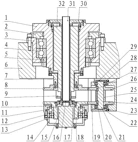
[0035] This embodiment is applicable to the mechanism for isolating strong and weak cables, including: main shaft 1, main bearing end cover 2, bearing seat 3, main shaft bearing 4, main lock nut 5, base body 6, encoder mounting shaft 7, active Gear 8, slip ring A fixed frame 9, adapter bracket 10, driven gear bearing 11, auxiliary bearing end cover 12, auxiliary lock nut 13, slip ring B bracket 14, slip ring B15, cable tube lower bracket 16, Slip ring B fixed frame 17, driven gear 18, gear box 19, flat key A20, reversing gear shaft 21, lower bearing end cover 22, gear bearing A 23, reversing gear A24, gear spacer 25, reversing gear B26, flat key B27, gear bearing B 28, upper bearing cover 29, cable tube upper bracket 30, cable tube 31, slip ring A32.

[0036] The main shaft 1 is a hollow structure, and forms the main shaft shaft system with the main bearing cover 2, the bearing seat 3, the main shaft bearing 4 and the main lock nut 5, and the bearing seat 3 is fixed on the bas...


PUM


Abstract

A single-shaft double-slip ring mechanism, including a main shaft shaft, a driven gear shaft, a reversing gear shaft, a slip ring A, a slip ring B, a cable tube, a cable tube lower bracket, and a cable tube upper bracket . The main shaft drives the slip ring A and the driving gear to rotate clockwise, and transmits the power to the reversing gear B. At this time, the direction of rotation of the reversing gear shaft system is counterclockwise; then the power is output through another parallel reversing gear A To the driven gear, and drive the slip ring B to rotate clockwise, realizing the function of installing two sets of slip rings on the same shafting and ensuring synchronous movement.

Description

technical field [0001] The invention relates to a single-shaft double-slip ring mechanism, in particular to a single-shaft double-slip ring mechanism applied to various instruments and meters and inertial navigation test equipment. Background technique [0002] In the development process of inertial navigation test equipment, isolation measures must be taken between the strong current and weak current cables to reduce the interference of strong current on weak current signals, which is conducive to the realization of the technical indicators of the entire product. [0003] In general, strong current cables refer to the cables of actuators (various motors), and weak current cables refer to the cables of various sensor devices. To achieve strong and weak current isolation for the cables inside the equipment, two technical difficulties need to be solved: [0004] 1. In the case of strong and weak electrical isolation, the continuous and infinite rotation of the shaft system mu...

Claims


Application Information

Patent Timeline
Patent Type & Authority Patents(China)
IPC IPC(8): H01R39/08H01R39/64
Inventor 付和平刘喜平贾军周志仁
Owner JIUJIANG PRECISION MEASURING TECH RES INST
Why Eureka
Try Eureka