Phase-change type heat storage device with built-in water tank

A heat storage device and water tank technology, applied in the field of heat storage, can solve problems such as damage to solder joints, large size, and installation difficulties, and achieve the effects of satisfying heating and hot water needs, stable phase transition process, and high space utilization.

Active Publication Date: 2015-10-21
PIONEER ENERGY JIANGSU
View PDF6 Cites 7 Cited by
  • Summary
  • Abstract
  • Description
  • Claims
  • Application Information

AI Technical Summary

Problems solved by technology

[0002] Due to the immature structural design of the inner tank and coil components of the existing phase change heat storage device, the heat exchange coil inside the heat storage device is not uniform, and the phase change material is not fully utilized, resulting in the existing phase change The heat exchange efficiency of the heat storage device is low, which indirectly increases the production cost of the product
The existing phase change heat storage device has the defect that the solder joint between the pipe fitting and the main channel in the heat exchange component is immersed in the phase change material, which caus

Method used


Image

  • Phase-change type heat storage device with built-in water tank
  • Phase-change type heat storage device with built-in water tank

Examples


Embodiment

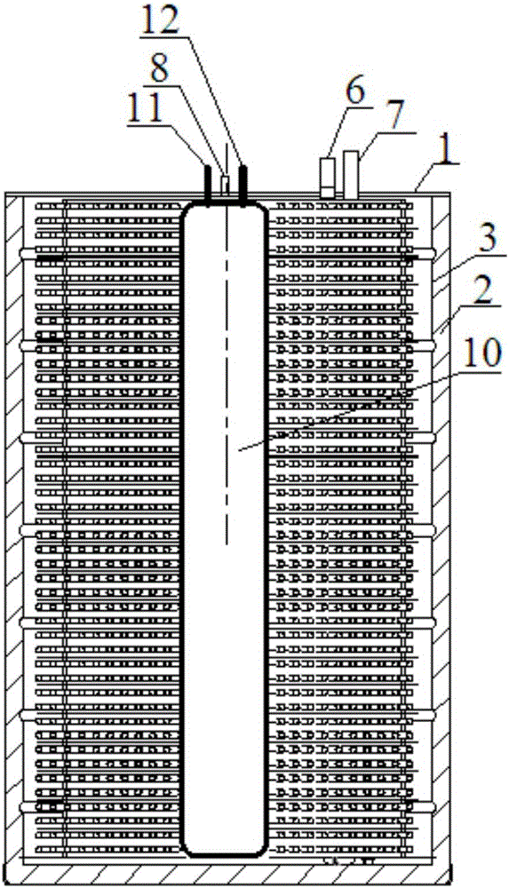
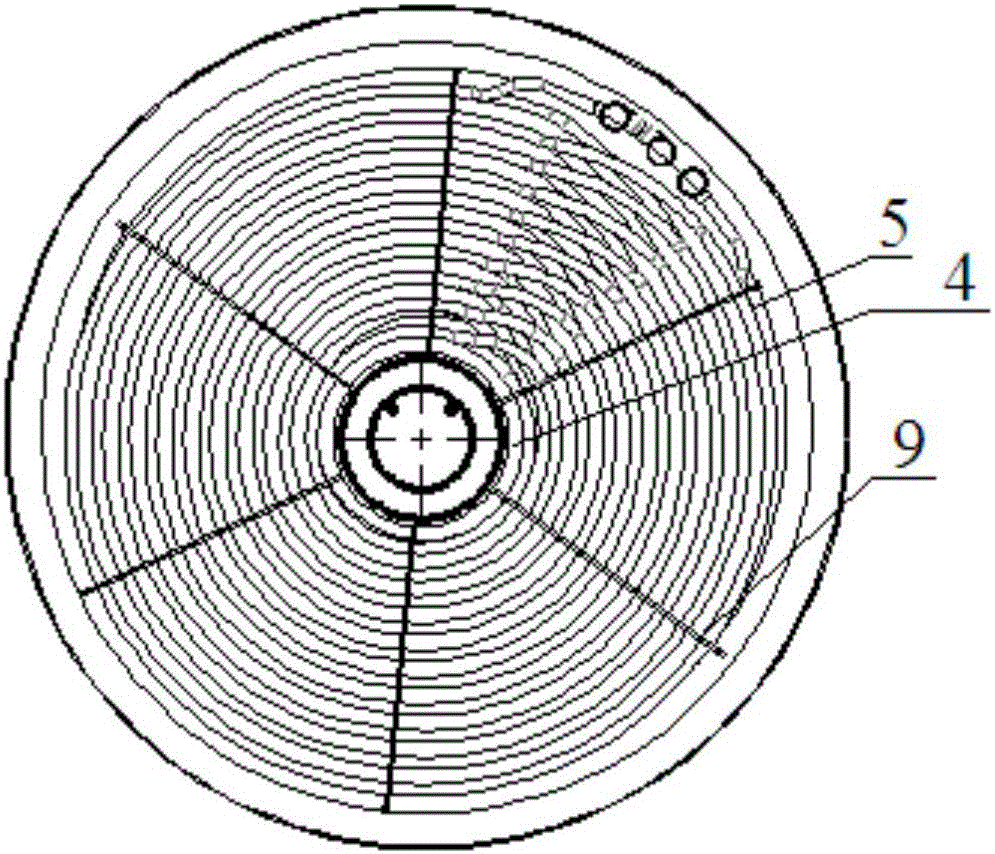
[0027] A phase-change heat storage device with a built-in water tank, such as figure 1 , figure 2 As shown, the outer shell 1 is included, the inner tank 3 is set in the outer shell 1, the insulation layer 2 is set between the inner tank 3 and the outer shell 1, the inner tank 3 is filled with a phase change material 4, and a heat exchange plate is embedded in the phase change material 4 The pipe 5 and the inlet and outlet of the heat exchange coil 5 extend to the outside of the inner tank 3, and are respectively connected to the main inlet pipe 6 and the main outlet pipe 7 by welding, and the main inlet pipe 6 and the main outlet pipe 7 are connected to the external heating pipe. System connection, the external system can provide stable and continuous heating or cooling. A built-in water tank 10 is arranged inside the liner 3, one end of the built-in water tank 10 is a cold water inlet pipe 11 for connecting tap water supply, the other end is a hot water outlet pipe 12 for ...


PUM


Abstract

The invention relates to a phase-change type heat storage device with a built-in water tank. The phase-change type heat storage device includes a shell, a liner arranged in the shell, a heat-insulating layer arranged between the liner and the shell; the liner is filled with a phase change material; a heat-exchange coil is buried in the phase change material; the inlet and outlet of the heat-exchange coil both extend out from the liner and are welded to and communicated with a water entering main pipeline and a water outgoing main pipeline respectively; the water entering main pipeline and the water outgoing main pipeline are connected with an external heat supply system; the built-in water tank is arranged in the liner; one end of the built-in water tank is provided with a cold water entering pipe; the other end of the built-in water tank is provided with a hot water outgoing pipe; and a space between the built-in water tank and the liner is filled with the phase change material. Compared with the prior art, the phase-change type heat storage device with the built-in water tank of the invention has the advantages of simple structure and high heat storage capacity, and can simultaneously meet heat and hot water demands. With the phase-change type heat storage device adopted, when the quantity of hot water is insufficient, the heat of the phase change material can be continuously provided for the inner tank; and the phase change process of the phase change material is stable, and therefore, the device can supply heat stably and continuously and can satisfy heating and hot water requirements of buildings.

Description

technical field [0001] The invention relates to the field of heat storage, in particular to a phase-change heat storage device with a built-in water tank. Background technique [0002] Due to the immature structural design of the inner tank and coil components of the existing phase change heat storage device, the heat exchange coil inside the heat storage device is not uniform, and the phase change material is not fully utilized, resulting in the existing phase change The heat exchange efficiency of the heat storage device is low, which indirectly increases the production cost of the product. The existing phase change heat storage device has the defect that the solder joint between the pipe fitting and the main channel in the heat exchange component is immersed in the phase change material, which causes the solder joint to be corroded by the phase change material and cause fatal damage, and the solder joint is immersed in the It is inconvenient to maintain after the solder ...

Claims


Application Information

Patent Timeline
IPC IPC(8): F28D20/02F28F21/00F28F23/00
CPCY02E60/14
Inventor 孙利王鋐刘晓龙王长君
Owner PIONEER ENERGY JIANGSU
Why Eureka
Try Eureka