
A vacuum structure folding door

A folding door and vacuum technology, applied in door leaves, fire doors, soundproof doors/windows, etc., can solve the problems of blocking sound and heat, the door leaf cannot be folded, and the sound insulation and sound absorption effect is poor, so as to block sound and heat. the effect of transmission

Active Publication Date: 2016-06-01
黄玉娇
View PDF7 Cites 0 Cited by
  • Summary
  • Abstract
  • Description
  • Claims
  • Application Information

AI Technical Summary

Problems solved by technology

[0002] The traditional roll-type folding door uses multiple blades to form the door body, and then rolls the multiple blades into a cylinder to achieve the purpose of folding. The gaps between these blades are very large, and the blades are single-layer blades. Forming a cavity for sound insulation and absorption, these folding doors do not allow the blades to form a heat and sound insulation layer, so the sound insulation and sound absorption effect is extremely poor
[0003] Patent application No. 201110033198.X discloses a folding door, which uses large leaves to fold together to form a door body, but this large leaf is a single-layer leaf, and sound and heat can easily penetrate the leaf, so it cannot achieve sound insulation The effect of heat insulation, this invention does not solve the problem of sound insulation and heat insulation of the door leaf structurally, and because there is a half leaf at the joint of the leaf, there is a gap between the half leaf and the leaf, which is easy to be caught by the hand and affects the appearance
Some door leaves are set in a multi-layer structure, using the middle interlayer to achieve sound insulation and heat insulation, but this kind of door leaf cannot realize the folding function, and these interlayers are not vacuum structures, so they cannot completely block sound and heat

Method used


Image

  • A vacuum structure folding door
  • A vacuum structure folding door
  • A vacuum structure folding door

Examples


Embodiment Construction

[0034] The present invention will be further described in detail below in conjunction with the accompanying drawings, so that those skilled in the art can implement it with reference to the description.

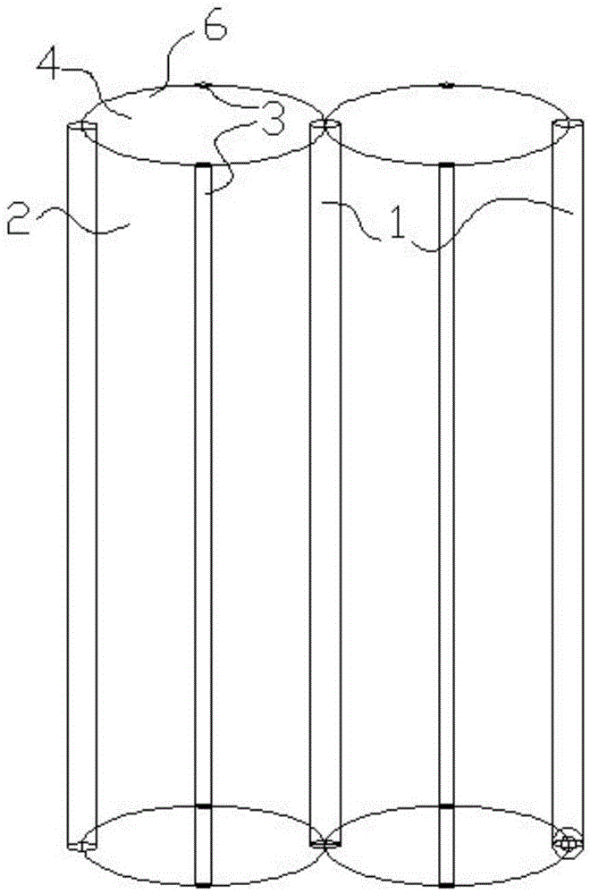
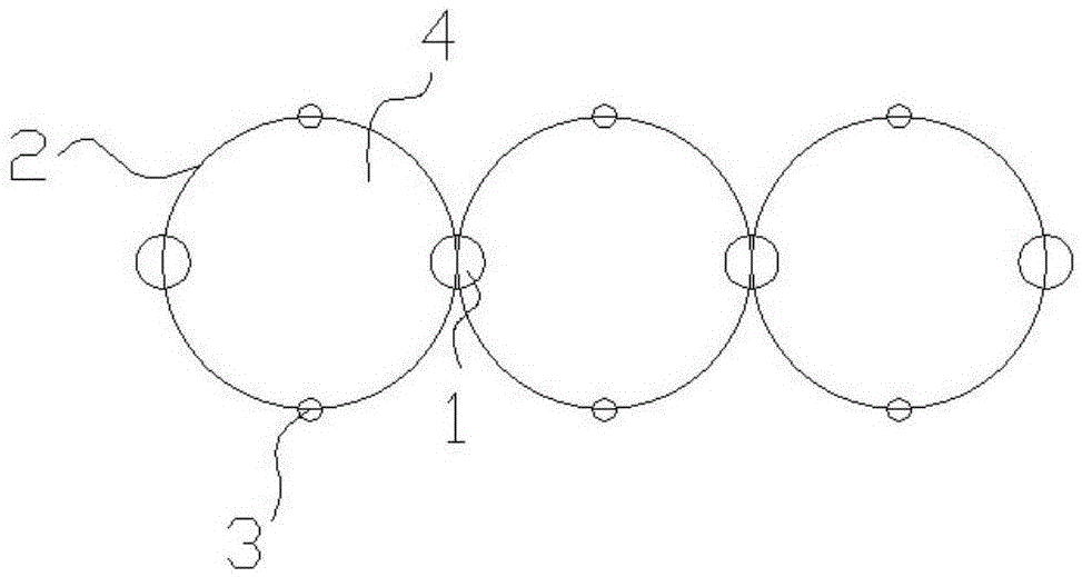
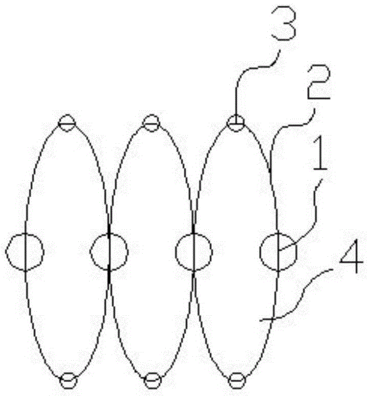
[0035] Such as figure 1 , 2 , 3 and 4, the first connecting shaft 1; it is vertically arranged, and the first connecting shaft 1 is the hinge point of the two door leaves 6, so the first connecting shaft 1 should be slightly larger than the second connecting shaft 3. Big.

[0036] The second connecting shaft 3; it is arranged in parallel with the first connecting shaft 1, which is the hinge point and joint of the two arc pages 2 in the door leaf 6, and the two arc pages 2 can surround the second connecting shaft 3 Turning, the folding and stretching between the two circular arc pages 2 have been realized.

[0037] At least two door leaves 6, the door leaves 6 are rotatably hinged on the first connecting shaft 1, and freely swing around the first connecting shaft 1; the two...


PUM


Abstract

The invention discloses a vacuum structure folding door which comprises a first connecting shaft, a second connecting shaft, at least two door hinges and a sliding rail. The door hinges are rotationally hinged to the first connecting shaft and swing freely with the first connecting shaft as the joint. Each door hinge is a geometric cylinder defined by at least four circular arc pieces, wherein a cavity is formed in the middle of the door hinge. The circular arc pieces are connected with one another with the second connecting shaft as the joint. The circular arc pieces are rotationally hinged to the joint to fold and stretch around the joint so that the door hinges can stretch and contract. The peripheries of the cavities are closed and are pumped to be in a vacuum state. According to the vacuum structure folding door, at least four circular arc pieces are rotationally hinged to the connecting shaft to form each door hinge with the cavity formed in the middle, and therefore the sound absorbing and heat insulating functions of the door hinges are improved; the cavities are pumped to be in the vacuum state to prevent transmission of sounds and heat, and therefore sound and heat insulation is more thorough.

Description

technical field [0001] The present invention relates to a kind of furniture, more specifically, the present invention relates to a kind of vacuum structure folding door capable of sound insulation and heat insulation. Background technique [0002] The traditional roll-type folding door uses multiple blades to connect to form the door body, and then roll the multiple blades into a cylinder to achieve the purpose of folding. The gaps between these blades are very large, and the blades are single-layer blades. Forming a cavity to block and absorb sound, these folding doors do not allow the blades to form a heat and sound insulation layer, so the sound insulation and sound absorption effect is extremely poor. [0003] Patent application No. 201110033198.X discloses a folding door, which uses large leaves to fold together to form a door body, but this large leaf is a single-layer leaf, and sound and heat can easily penetrate the leaf, so it cannot achieve sound insulation The ef...

Claims


Application Information

Patent Timeline
Patent Type & Authority Patents(China)
IPC IPC(8): E06B3/48E06B3/70E06B5/16E06B5/20
Inventor 黄玉娇
Owner 黄玉娇
Learn More