
Glove vane aircraft

A fan-wing and aircraft technology, applied in the field of fan-wing aircraft, can solve the problems of low efficiency of roller conversion lift, long runway, etc.

Active Publication Date: 2015-10-21
XIAN AIRCRAFT DESIGN INST OF AVIATION IND OF CHINA
View PDF7 Cites 4 Cited by
  • Summary
  • Abstract
  • Description
  • Claims
  • Application Information

AI Technical Summary

Problems solved by technology

[0004] Due to the coupling of thrust and lift of the fan wing, when the take-off weight increases, a relatively long run distance is required for take-off by roll alone, that is, a very long runway is required, that is, using the existing technology, the lift efficiency of the roller conversion during take-off is equivalent low

Method used


Image

  • Glove vane aircraft

Examples


Embodiment Construction

[0021] In order to make the objectives, technical solutions and advantages of the present invention clearer, the technical solutions in the embodiments of the present invention will be described in more detail below in conjunction with the drawings in the embodiments of the present invention. In the drawings, the same or similar reference numerals denote the same or similar elements or elements having the same or similar functions throughout. The described embodiments are some, but not all, embodiments of the invention. The embodiments described below by referring to the figures are exemplary and are intended to explain the present invention and should not be construed as limiting the present invention. Based on the embodiments of the present invention, all other embodiments obtained by persons of ordinary skill in the art without creative efforts fall within the protection scope of the present invention. Embodiments of the present invention will be described in detail below ...


PUM


Abstract

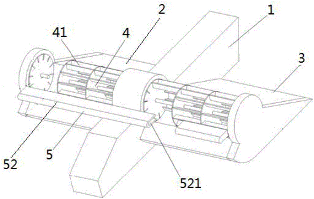
The invention discloses a glove vane aircraft. The glove vane aircraft comprises a first glove vane (2) and a second glove vane (3) which are symmetrical to each other about an aircraft body (1). Glove vane rollers (4) are arranged on the first glove vane (2) and the second glove vane (3). In the aircraft running state, roller bodies (41) in the glove vane rollers (4) bear air flow opposite to the running direction of the aircraft. The glove vane aircraft is characterized in that the glove vane aircraft further comprises a high lift device (5) which is arranged on the air inlet sides of the glove vane rollers (4) and used for providing a power source for the glove vane rollers (4), and therefore the glove vane rollers (4) can obtain extra power. Due to the adoption of the structure, for the same glove vane aircraft, the running distance of the glove vane aircraft can be greatly reduced, and in other words, the glove vane roller lift force conversion efficiency of the glove vane aircraft is improved.

Description

technical field [0001] The invention relates to the technical field of fan-wing aircraft, in particular to a fan-wing aircraft. Background technique [0002] Fan-wing aircraft usually generate lift through the first wing on the fuselage and the fan rollers provided on the second wing. Specifically, the principle of lift generated by fan-wing aircraft is that when the roller rotates, a vortex will be formed inside the roller. With the increase of the incoming flow velocity, the center of the vortex will be shifted backward from the axial direction of the roller. After the shift, a lift. [0003] This process requires the fan-wing aircraft to move relative to the airflow. When taking off, it needs to accelerate to a certain speed to obtain enough lift. Simply put, fan-wing aircraft need a certain runway to accelerate to obtain the lift required for takeoff. [0004] Due to the coupling of thrust and lift of the fan wing, when the take-off weight increases, a relatively long...

Claims


Application Information

Patent Timeline
IPC IPC(8): B64C3/00B64C39/00
Inventor 李悦立陈涛李军府谭蓉蓉
Owner XIAN AIRCRAFT DESIGN INST OF AVIATION IND OF CHINA
Learn More