Reradiation antenna and wireless charger

A wireless charger and re-radiation technology, applied in the direction of antenna, resonant antenna, antenna coupling, etc., can solve the technical application problems that affect electronic equipment and difficult to use repeaters

Active Publication Date: 2015-10-14
LG ELECTRONICS INC
View PDF7 Cites 3 Cited by
  • Summary
  • Abstract
  • Description
  • Claims
  • Application Information

AI Technical Summary

Problems solved by technology

However, because the technology using repeaters radiates electromagnetic waves, the technology may affect surrounding electronic devices
In particular, for vehicles in which electronics are centrally located, different electronics may also be affected
In addition, it is difficult to apply the technology using repeaters to various communication standards including frequencies of different bands

Method used


Image

  • Reradiation antenna and wireless charger
  • Reradiation antenna and wireless charger
  • Reradiation antenna and wireless charger

Examples


Embodiment Construction

[0035] With reference to the accompanying drawings, a description will now be given in detail of the embodiments disclosed herein. For brief description with reference to the drawings, the same or equivalent components may be provided with the same reference numerals, and descriptions thereof will not be repeated. Generally, suffixes such as "module" and "unit" may be used to refer to elements or components. The use of such suffixes herein is intended to facilitate the description of the specification only, and the suffixes themselves are not intended to be assigned any particular meaning or function.

[0036] The accompanying drawings are used to help easily understand various technical features and do not limit the embodiments presented herein. As such, the present disclosure should be construed to extend also to any changes, equivalents and substitutions, except those specifically stated in the drawings. Although the terms first, second, etc. to illustrate various element...


PUM


Abstract

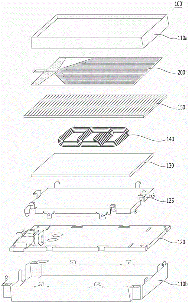
A reradiation antenna including an insulation panel; a ground contact formed on one side of the insulation panel; a slot formed by eliminating a part of the ground contact by exposing the insulation panel; a power feeding unit formed on the insulation panel between the slot and separated from the ground contact and connected with a power source using a first end of the power feeding unit; and a radiation unit formed on one side of the insulation panel, and connected with a second end of the power feeding unit positioned at an opened end of the slot.

Description

[0001] This application claims the benefit of priority to US Provisional Patent Application No. 61 / 974,411 filed April 2, 2014, which is hereby incorporated by reference in its entirety as if fully set forth herein. This application claims the benefit of priority of Korean Application No. 10-2014-0049192 filed on April 24, 2014 and Korean Application No. 10-2014-0082355 filed on July 2, 2014 and the priority of the earlier filing date rights, which are hereby incorporated by reference in their entirety as if fully set forth herein. technical field [0002] The present invention relates to a reradiation antenna capable of receiving radio signals and reradiating radio signals and a wireless charger equipped with wireless charging performance not degraded by the reradiation antenna. Background technique [0003] Recently, due to high-rise buildings and complicated interior spaces, radio shadow areas where the propagation environment is poor in wireless communication systems are...

Claims


Application Information

Patent Timeline
Patent Type & Authority Applications(China)
IPC IPC(8): H01Q1/36H01Q1/27H02J17/00
CPCH01Q9/0407H01Q1/22H01Q1/3291H01Q1/48H01Q1/52H01Q5/364H01Q9/40H01Q21/30H02J7/025H04B5/0075H01Q1/27H01Q1/36H04B5/79H04B5/24H02J50/70H02J50/90H02J50/12
Inventor 权在纯徐丁教黄注盛
Owner LG ELECTRONICS INC
Why Eureka
Try Eureka