Integral PSS etching tray fixture

An integral, tray technology, used in semiconductor/solid-state device manufacturing, electrical components, circuits, etc., can solve problems such as changes in equipment hardware structure, the cost and workload of transformation, and improve work efficiency, easy operation, and edge effects. improved effect

Inactive Publication Date: 2015-10-14
HAIDIKE NANTONG OPTOELECTRONICS TECH CO LTD
View PDF6 Cites 2 Cited by
  • Summary
  • Abstract
  • Description
  • Claims
  • Application Information

AI Technical Summary

Problems solved by technology

If it is necessary to replace the type of fixture, it will inevitably involve changes in the hardware structure of the equipment, and the cost and workload of the transformation will increase significantly

Method used


Image

  • Integral PSS etching tray fixture
  • Integral PSS etching tray fixture
  • Integral PSS etching tray fixture

Examples


Embodiment 1

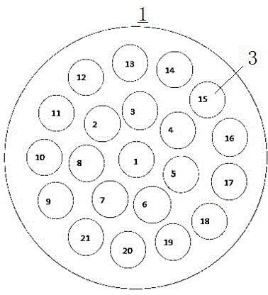
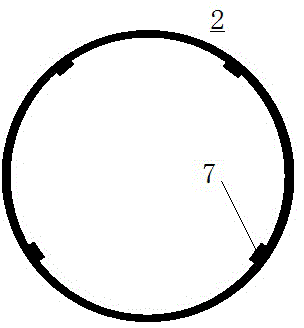
[0024] See attached figure 1 to attach Figure 4 as shown, figure 1 Described the front view of the integrated tray of the integrated PSS etching tray jig according to the present invention, figure 2 A partial cross-sectional view of the integral tray of the integral PSS etching tray jig according to the present invention is described, image 3 The front view of the pressure ring of the integrated PSS etching tray fixture according to the present invention is described, Figure 4 A partial cross-sectional view of the pressure ring of the integrated PSS etching tray jig according to the present invention is described.

[0025] The integrated PSS etching tray jig of the present invention comprises an integral tray 1 and a pressure ring 2 made of a metal material, and the material of the integral tray 1 is not limited (it can be quartz, metal, or ceramics), but the monolithic tray 1 must be a monolithic structure.

[0026] In order to ensure that wafers can be placed, it is...

Embodiment 2

[0031] See attached Figure 5 as shown, Figure 5 A front view of the pressure ring of the integral PSS etching tray jig in another embodiment is described. The pressure ring in this embodiment is generally similar to the structure of the pressure ring in Embodiment 1. The difference is that the actual wafer is often not absolutely circular, but has a positioning edge. Therefore, the corresponding slot 3 Both the pressure ring 2 and the pressure ring 2 need to design the positioning edge 8.

[0032] In addition, according to the design accuracy and the effect in actual use, the inner diameter of the slot 3 can be selected for placing the sealing ring, so as to enhance the sealing performance of the side part.


PUM


Abstract

The invention discloses an integral PSS etching tray fixture, which comprises an integral tray and press rings made of metal, wherein the integral tray is provided with multiple wafer grooves; each wafer groove is internally provided with a step for placing a wafer; a cooling cavity is arranged below the step in the wafer groove; the cooling cavity is provided with multiple cooling holes; the cooling holes are communicated with a cooling gas; each press ring is arranged above the wafer inside each wafer groove; and the press ring is annular and covers the circumferential edge of the wafer. By adopting the above technical scheme, advantages of a quartz element and advantages of a metal element are combined, edge effects can be well improved, no extra tools such as a positioning disc need to be used, sealing material such as vacuum grease does not need to be used, the operation is simple and convenient, the work efficiency can be improved, and labor cost is saved.

Description

technical field [0001] The invention belongs to the technical field of semiconductors. Background technique [0002] The object of PSS etching is sapphire substrate, which belongs to the micron-scale processing technology. One of the process requirements is high uniformity (<3%) in the chip, especially the pattern of the edge area should be symmetrical and there should be no adhesion. With the continuous improvement of industry standards, more and more attention has been paid to the quality of the edge area, followed by the ability to deal with edge issues constitutes the core competitiveness of each PSS manufacturer, and even ICP equipment manufacturers, and in this process The middle pallet fixture is the key factor affecting the edge problem. [0003] At present, the pallets used for PSS etching on the market have the following two structures. [0004] Structure 1: metal tray with quartz cover. The advantage of this jig is that the manufacturing process is simple an...

Claims


Application Information

Patent Timeline
Patent Type & Authority Applications(China)
IPC IPC(8): H01L21/673
CPCH01L21/673
Inventor 魏臻孙智江贾辰宇
Owner HAIDIKE NANTONG OPTOELECTRONICS TECH CO LTD
Why Eureka
Try Eureka