
Capacitor cover flip push device

A capacitor cover and push device technology, applied in capacitors, capacitor manufacturing, circuits, etc., can solve the problems of reduced capacitor efficiency, high labor costs, and affecting product quality, and achieve the effect of improving efficiency and filling the gap in the industry

Inactive Publication Date: 2017-10-20
WUHAN POLYTECHNIC UNIVERSITY
View PDF9 Cites 0 Cited by
  • Summary
  • Abstract
  • Description
  • Claims
  • Application Information

AI Technical Summary

Problems solved by technology

[0004] Figure 11 It is a schematic diagram of the state of the cover plate before turning over. In the process of preparing the capacitor, it is necessary to remove the cover plate from Figure 11 state flipped to Figure 12 However, in the current production process, when the ends of the two guide foils are riveted on the cover plate, the cover plate is manually turned 90° from the horizontal position and then pushed to the battery inside the aluminum shell The front end, so as to close the opening of the aluminum shell, and this method of manually pushing the cover plate to the battery cell is time-consuming and laborious, and also affects product quality, greatly reducing the efficiency of producing capacitors, and the labor cost is also high. Not suitable for the needs of modern production development

Method used


Image

  • Capacitor cover flip push device
  • Capacitor cover flip push device
  • Capacitor cover flip push device

Examples


Embodiment Construction

[0048] In order to make the purpose, technical solutions and advantages of the present invention clearer, the following technical solutions in the present invention are clearly and completely described. Obviously, the described embodiments are some embodiments of the present invention, rather than all embodiments. Based on the embodiments of the present invention, all other embodiments obtained by persons of ordinary skill in the art without creative efforts fall within the protection scope of the present invention.

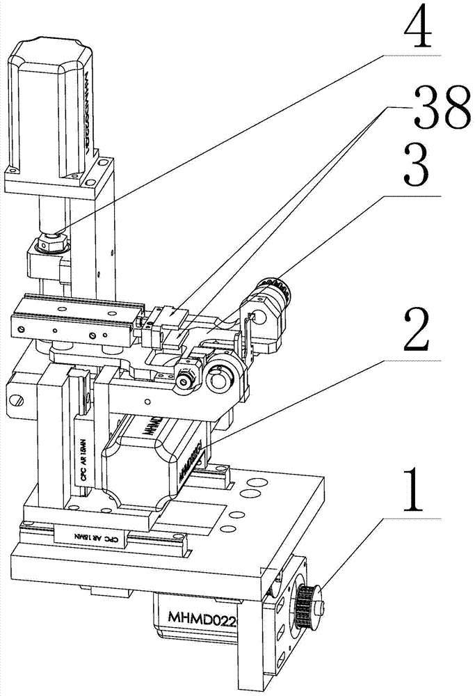
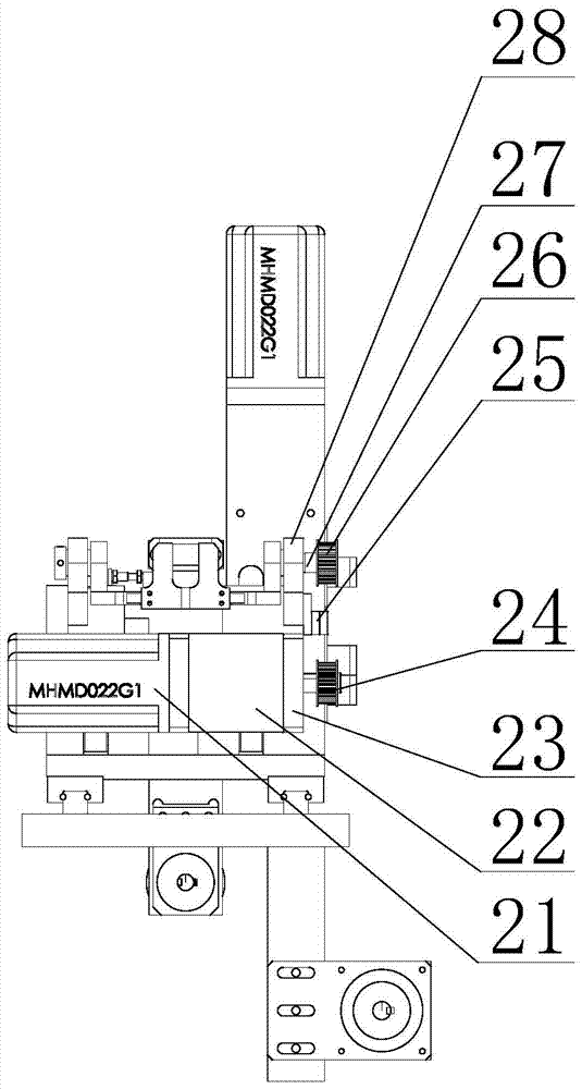
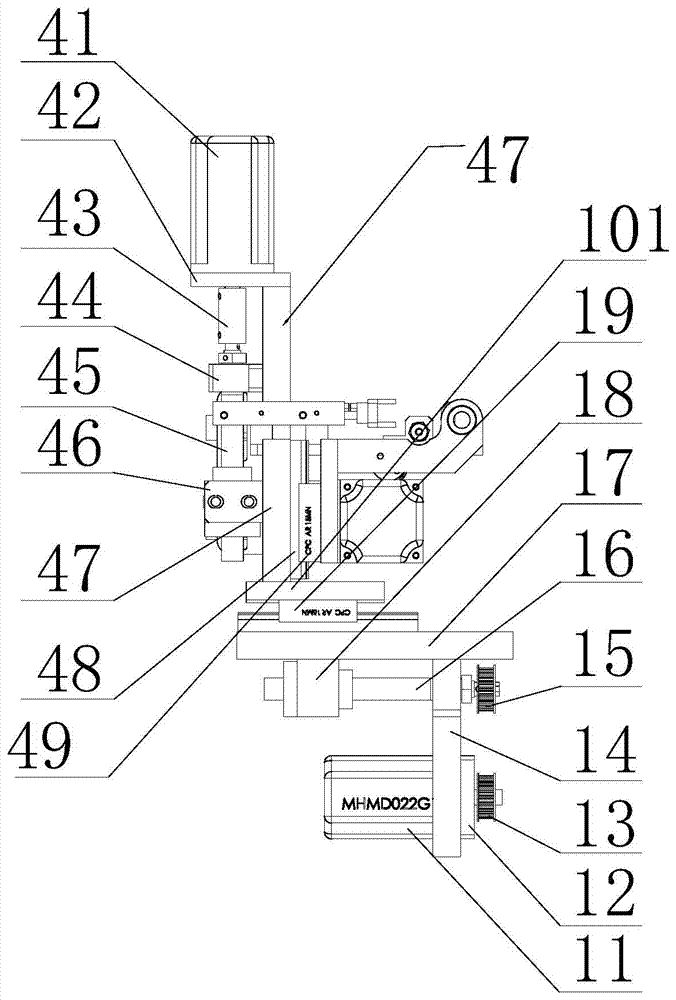
[0049] Such as figure 1 As shown, the capacitor cover flipping and pushing device provided by the present invention includes: a forward and backward moving device 1 , a 90° rotating device 2 , a clamping device 3 , and an up and down moving device 4 . Among them, the clamping device shown is used to clamp the cell horizontally to facilitate the flipping of the cover; the 90°rotation device is used to realize the cover from Figure 11 gesture becomes Figure 12 ...


PUM


Abstract

The invention provides a flipping and pushing device for a capacitor cover plate, comprising: a forward and backward moving device, a 90° rotating device, a clamping device, and an up and down moving device; the clamping device is used to clamp the cover plate riveted with a battery core; The 90° rotating device is used to turn over the clamping device installed on it; the up and down moving device is used to drive the 90° rotating device installed on it to move up and down; the forward and backward moving device is used to drive the The up and down moving device on it moves back and forth; the 90° rotating device, the clamping device, and the up and down moving device are installed on the upper surface of the front and rear guide rail connecting plates; the front and rear moving devices are installed on the lower surface of the front and rear guide rail connecting plates. The invention realizes the fully automatic operation of flipping the cover plate from the horizontal position to the vertical position and ensures the bonding of the cover plate and the front surface of the battery cell, fills the gap in the industry of lack of automatic cover plate flipping, and greatly improves the efficiency of the capacitor packaging process.

Description

technical field [0001] The invention relates to the technical field of machinery, in particular to a flipping and pushing device for a capacitor cover plate. Background technique [0002] At present, the phenomenon that the inspection index of domestic capacitor finished products is lower than the design index has become common in many enterprises. The reason is that the production process and production equipment are far behind those of foreign countries. Among them, the capacitor production equipment uses a single machine to produce a specific function, there are many intermediate links, and the environment changes greatly, so it is impossible to organize and arrange production according to uniform standards. Especially in the research of capacitor feeding principle and packaging technology, although domestic scholars have made some progress in the research of cylindrical material (capacitor) feeding and packaging technology, they are all limited to single-machine improvem...

Claims


Application Information

Patent Timeline
Patent Type & Authority Patents(China)
IPC IPC(8): H01G13/00B65G25/08
Inventor 张国全雷新云王娈刘佳王帆明文郭宁
Owner WUHAN POLYTECHNIC UNIVERSITY
Learn More