
Optical switching device and straight-down type LED lamp with same

A technology of LED lamps and adapters, which is applied in the direction of optics, optical components, lighting devices, etc., can solve the problems of invaluability, high cost of flexible light source boards, certain problems in reliability and installation difficulty, and avoid graininess, The effect of compact structure and wide applicability

Inactive Publication Date: 2015-10-14
OPPLE LIGHTING
View PDF8 Cites 1 Cited by
  • Summary
  • Abstract
  • Description
  • Claims
  • Application Information

AI Technical Summary

Problems solved by technology

In the case of straight sides such as rectangular light guide elements, the structure setting and optical path setting of the side-mounted LED light source will not cause too many problems, but when the coupling surface is a curved surface or a circular surface, the side-mounted LED light source The backlighting method of the type LED light source requires the use of a flexible light source board. Because the cost of the flexible light source board is relatively expensive, and there are certain problems in reliability and installation difficulty, there are still many unassessable risks. This has become a side-mounted LED light source. development constraints

Method used


Image

  • Optical switching device and straight-down type LED lamp with same
  • Optical switching device and straight-down type LED lamp with same
  • Optical switching device and straight-down type LED lamp with same

Examples


Embodiment Construction

[0055] The advantages of the present invention will be further elaborated below in conjunction with the accompanying drawings and specific embodiments.

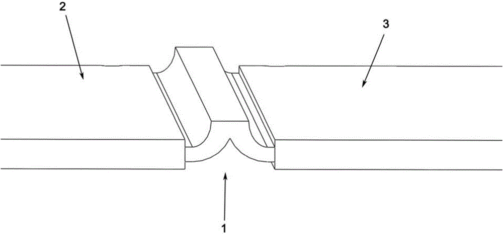
[0056] like figure 1 Shown is an optical transition device 1 according to a preferred embodiment of the present invention, which is used to deflect light into at least one light guide element, wherein the cross section of the optical transition device 1 is roughly "herringbone", mainly to The light emitted by the light source propagates to the adjacent light guide element through the reflection in the optical transition device 1 to realize surface emission.

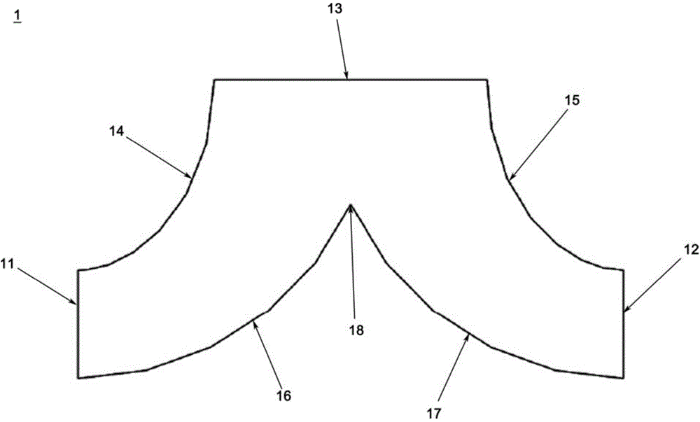
[0057] like figure 2 A schematic cross-sectional view of an optical transition device 1 according to a preferred embodiment of the present invention is shown, the optical transition device 1 includes opposite first and second surfaces, and light-emitting surfaces 11 and 12 connecting the first and second surfaces , the first surface includes the light incident surface...


PUM


Abstract

The invention provides an optical switching device. The optical switching device is used for shifting light to at least one light guide element. The optical switching device comprises a first surface and a second surface which are opposite to each other, and a light outgoing surface connected with the first surface and the second surface; the first surface includes a light incoming surface and an outer connecting surface connected with the light incoming surface and the light outgoing surface; the second surface is recessed towards the light incoming surface to a deepest recessed portion and includes an inner connecting surface; the inner connecting surface extends from the deepest recessed portion and stops at the light outgoing surface; the light outgoing surface and the light guide element are opposite to each other at least partially; and light received by the light incoming surface is reflected by the outer connecting surface and the inner connecting surface by many times, and then, is coupled by the light outgoing surface, and enters the light guide element. The invention also provides a straight-down type LED lamp. The straight-down type LED lamp comprises at least one light guide element, at least one optical switching device and at least one light emitting assembly; one light emitting assembly is correspondingly arranged on the light incoming surface of one optical switching device; the light guide element surrounds the light outgoing surface or an end portion of the light guide element at least partially faces the light outgoing surface.

Description

technical field [0001] The invention relates to the field of light guide elements, in particular to an optical transfer device. [0002] The invention also relates to a direct-lit LED lamp with the optical transition device. Background technique [0003] The current application of LED light sources in the field of backlight light sources is mainly divided into direct-type LED lamps and side-mounted LED light sources, of which side-mounted LED light sources are the mainstream in the market. In the case of straight sides such as rectangular light guide elements, the structure setting and optical path setting of the side-mounted LED light source will not cause too many problems, but when the coupling surface is a curved surface or a circular surface, the side-mounted LED light source The backlighting method of the type LED light source requires the use of a flexible light source board. Because the cost of the flexible light source board is relatively expensive, and there are c...

Claims


Application Information

Patent Timeline
Patent Type & Authority Applications(China)
IPC IPC(8): G02B6/00F21S2/00F21V8/00F21Y101/02
CPCG02B6/0001F21S2/00
Inventor 尹松陈明
Owner OPPLE LIGHTING
Learn More