
Air inlet and ignition integrated valve for commercial gas stove

A gas stove, commercial technology, used in household stoves/stoves, applications, valve details, etc., can solve problems such as inconvenient operation and hidden safety hazards

Inactive Publication Date: 2015-10-14
WUHAN UNITE KITCHEN EQUIP FABTION
View PDF8 Cites 3 Cited by
  • Summary
  • Abstract
  • Description
  • Claims
  • Application Information

AI Technical Summary

Problems solved by technology

[0004] The technical problem to be solved by the present invention is to provide an air intake and ignition integrated valve for commercial gas stoves, so as to overcome the defects of inconvenient operation and potential safety hazards in the prior art

Method used


Image

  • Air inlet and ignition integrated valve for commercial gas stove
  • Air inlet and ignition integrated valve for commercial gas stove
  • Air inlet and ignition integrated valve for commercial gas stove

Examples


Embodiment 1

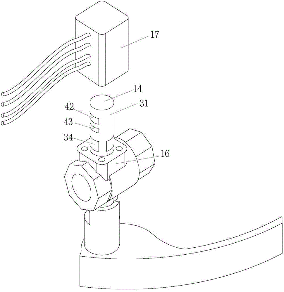
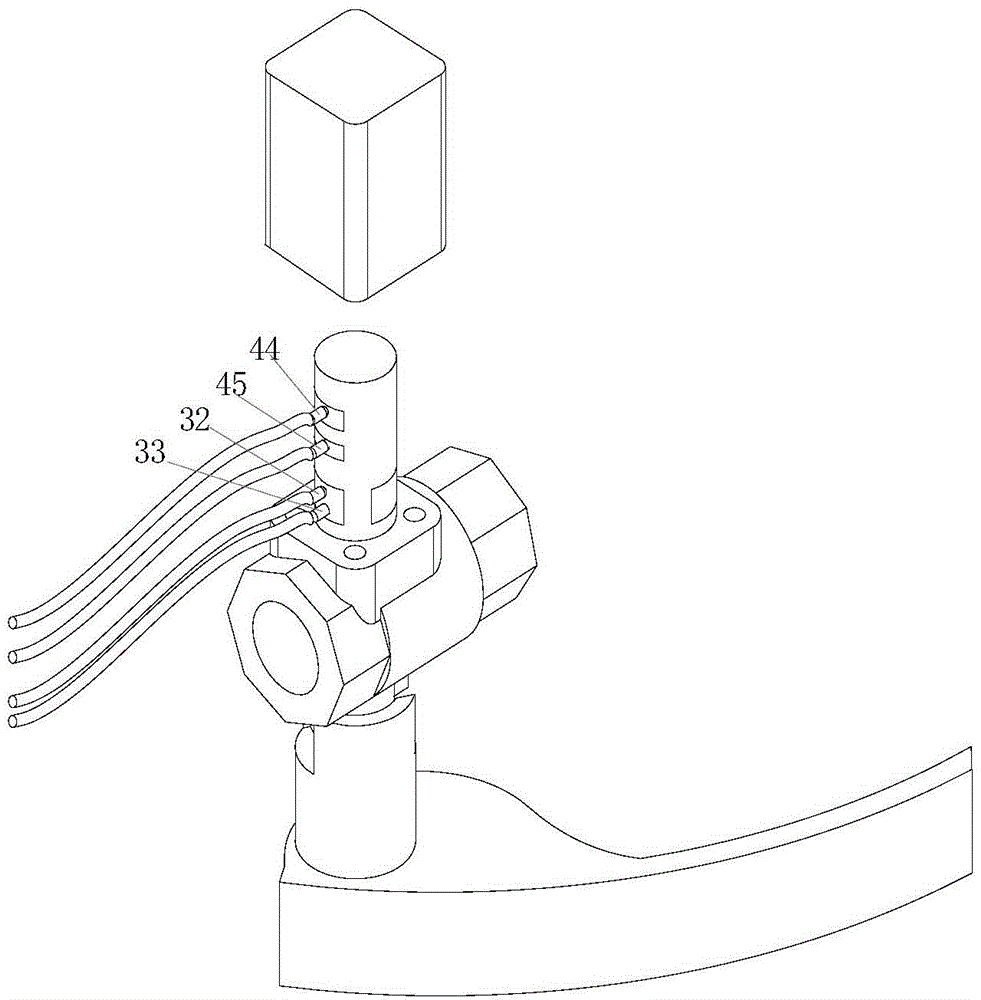
[0034] The switch is turned on when the valve is closed, and the switch is closed when the valve is opened. The principle is as follows: Figure 6 As shown, when the valve is closed, the rotation angle of the valve stem is in the 0 state, and at this time the conductive contacts 32, 33 are all on the first conductor slip ring segment 34, and the two ends of the conductive contacts 32, 33 are connected, that is to control the open state of the switch.

[0035] When the valve stem rotation angle is greater than 0° during the valve opening process, such as Figure 7 As shown, at this time, the conductive contacts 32, 33 are on the insulator 31, and the two points of the contacts 32, 33 are not conducting. At this time, the control switch is in the closed state.

Embodiment 2

[0037] When the valve is not fully open, the control switch is closed; when the valve is fully open at 90°, the control switch is open, the principle is as follows Figure 8 shown. When the valve is not fully opened, the conductive contacts 32, 33 are on the insulator 31, and the two points of the contacts 32, 33 are not conducting, which is the closed state of the control switch.

[0038] When the stem rotation angle is 90°, such as Figure 9 As shown, the valve is opened in the fully open state. At this time, the conductive contacts 32, 33 are all on the first conductor slip ring segment 34. At this time, the two ends of the conductive contacts 32, 33 are connected, which is the open state of the control switch.

[0039] 3. The principle of the potentiometer switch is as follows:

[0040] Such as Figure 10As shown, when the valve is closed, the rotation angle of the valve stem is 0°, the conductive contacts 44, 45 are on the insulator 41 outside the second conductive rin...


PUM


Abstract

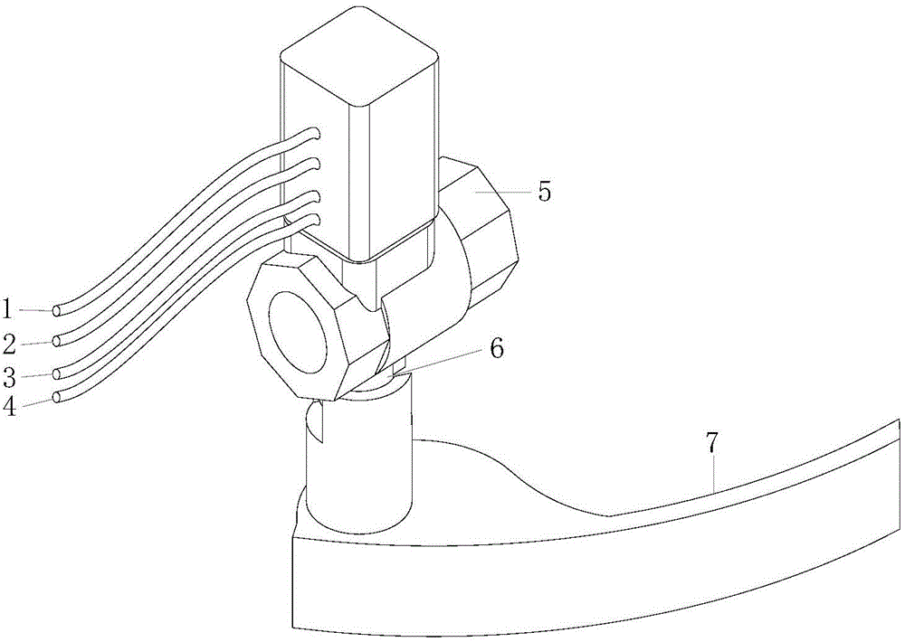
The invention discloses an air inlet and ignition integrated valve for a commercial gas stove. A valve rod is connected with a valve element. The valve element is connected with a driven shaft located outside the valve body. The cylindrical surface of the driven shaft is provided with an insulation layer. The insulation layer is provided with a first conductor sliding ring section. A contact fixing cover is arranged outside the driven shaft and is fixedly connected to the valve body. A first conduction contact and a second conduction contact which are arranged in an up-and-down mode are arranged in the contact fixing cover. The first conduction contact and the second conduction contact are in contact with a cylindrical ring face where a first conductor sliding ring section is located. The first conduction contact and the second conduction contact are connected with an ignition control circuit through signal lines. According to the air inlet and ignition integrated valve for the commercial gas stove, an ignition control device microswitch is integrated on the air inlet valve, and when the air inlet valve is opened, the gas stove ignites automatically; an auxiliary external microswitch for controlling the gas stove is integrated at the same time, an interlocking effect between the gas inlet valve and the external auxiliary equipment is generated, and therefore an optimal matching effect can be achieved between gas supply and the external equipment.

Description

technical field [0001] The invention relates to a commercial gas stove, in particular to an air intake and ignition control valve for a commercial gas stove. Background technique [0002] Refers to the large-scale burning appliances used by hotels, guesthouses, restaurants, restaurants, government agencies, schools, military, hospital canteens and other groups that use various gases such as petroleum gas and natural gas as energy sources to directly heat cooking utensils. Most of the existing commercial gas stoves adopt the way of ignition and air intake valve separation. When using commercial gas stoves, the operator needs to press and hold the ignition switch while opening the air intake valve, and the left and right hands cooperate to operate. It is easy to produce the phenomenon that the ignition does not catch, or the phenomenon of ignition and deflagration, so it is very inconvenient to use, and there is also a certain potential safety hazard. [0003] Publication No....

Claims


Application Information

Patent Timeline
Patent Type & Authority Applications(China)
IPC IPC(8): F16K31/44F24C3/10
CPCF16K31/44F24C3/103
Inventor 李建堂
Owner WUHAN UNITE KITCHEN EQUIP FABTION
Learn More