
submersible power plant for generating electricity

A power plant, submersible technology, applied in the field of power plant, can solve the problems of low speed, inability to effectively utilize the available energy of fluid flow, etc., and achieve the effect of good energy extraction

Active Publication Date: 2019-06-04
MINESTO
View PDF6 Cites 0 Cited by
  • Summary
  • Abstract
  • Description
  • Claims
  • Application Information

AI Technical Summary

Problems solved by technology

This results in slower than necessary speeds of the vehicle in different parts of the trajectory, making efficient use of the energy available in the fluid flow

Method used


Image

  • submersible power plant for generating electricity
  • submersible power plant for generating electricity
  • submersible power plant for generating electricity

Examples


Embodiment Construction

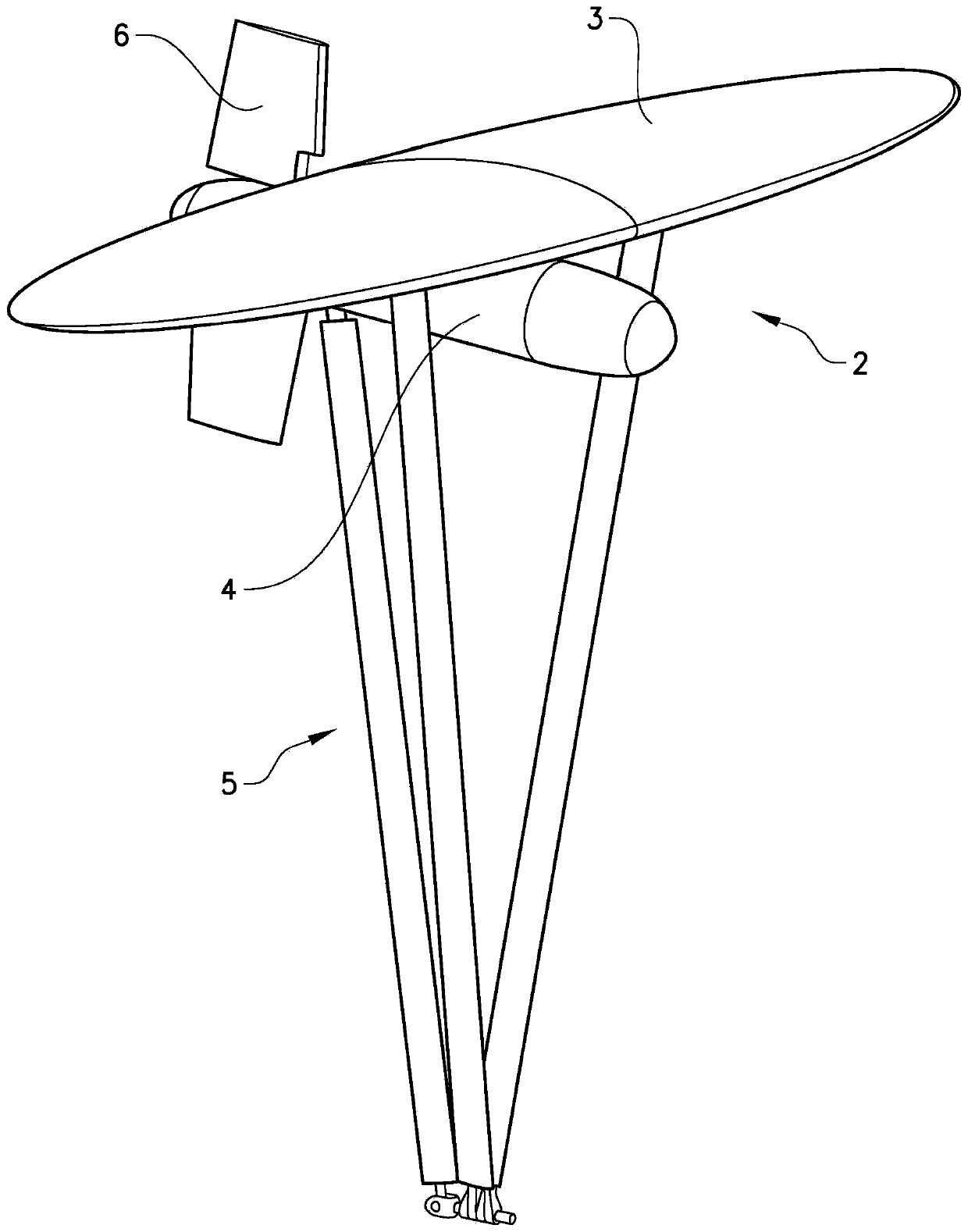
[0032] figure 1 A vehicle 2 of a power plant according to the invention is schematically shown. The vehicle 2 comprises a wing 3 , at least one pod 4 , at least one strut 5 and at least one control surface 6 . Depending on the configuration of the power plant, the vehicle 2 may also be equipped without the cabin 4 and one or more struts 5 .

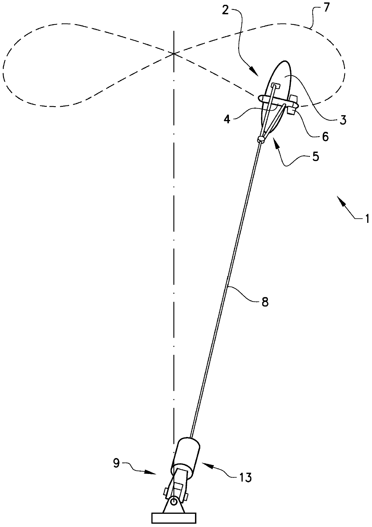
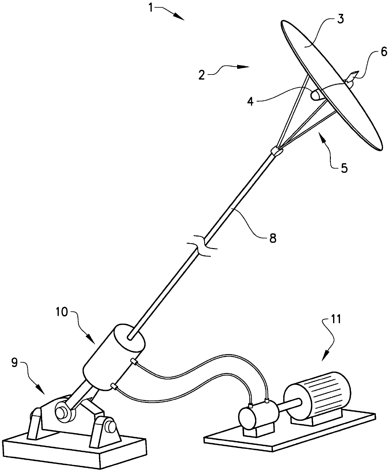
[0033] figure 2 A power plant 1 according to the invention is schematically shown with a vehicle 2 moving along a predetermined trajectory 7 . remove figure 1 In addition to the vehicle 2 described in , the power plant 1 also includes a tether 8 for attaching the vehicle 2 to a structure 9 . The structure 9 may be positioned on or fastened to a surface (eg any ground or the bottom of a sea, lake or ocean). The structure 9 is positioned above the surface of a sea, lake, river or ocean with submerged vehicles. Accordingly, the power plant 1 according to the invention can be used both on land and underwater. The power plant 1 also co...


PUM


Abstract

The invention relates to a power plant (1) for generating electric power. The power plant (1) comprises a vehicle (2) comprising at least one wing (3) arranged to be fixed to a structure (9) by means of at least one tether (8). The vehicle (2) is arranged to move on a predetermined trajectory (7) at varying speeds by means of fluid flow through the wings (3). Said power unit (1) comprises an element (13) arranged to continuously vary said vehicle (2) in relation to said predetermined trajectory (7) or during part of said predetermined trajectory. the distance between the structures (9) or allow the distance to be varied, thereby reducing the speed variation of the vehicle (2) on the predetermined trajectory (7) and / or allowing A transducer (10) of the power unit (1) generates electricity from said change in distance. An advantage of the invention is that it enables an increase in the efficiency of the power plant.

Description

technical field [0001] The present invention relates to power plants for generating electrical power. The power plant includes a structure and a vehicle (vehicle) including at least one wing. The vehicle is arranged to be secured to the structure by means of at least one tether. The vehicle is configured to move on a predetermined trajectory by fluid flow through the wings. The vehicle is arranged to move on a predetermined trajectory at varying speeds. Background technique [0002] Power plants are known in the art in the form of vehicles that are moved by fluid flow through the vehicle. The vehicle can be attached to a tether to be secured at a fastening point. The vehicle is then moved along the trajectory, and the kinetic energy in the fluid flow can be converted into electrical energy by suitable means. [0003] Trajectories can cause variations in velocity due to differences in fluid dynamics acting on the vehicle, or the velocity of the vehicle needs to be constr...

Claims


Application Information

Patent Timeline
Patent Type & Authority Patents(China)
IPC IPC(8): F03B13/10F03B13/26F03B15/00F03D5/00
CPCF03D5/00F03B13/264F03B17/06F05B2240/917Y02E10/70Y02E10/728F05B2240/921Y02E10/30F05B2240/9174Y02E10/20F03B3/04F03B13/10F03B15/00H02K7/1876
Inventor 奥洛夫·马泽柳斯阿尔内·夸彭
Owner MINESTO
Learn More