Improved structure of cover plate of heat radiator for LED lamp

A radiator cover and LED lamp technology, applied in lighting and heating equipment, cooling/heating devices of lighting devices, lighting devices, etc., can solve the problems of reduced contact area between aluminum substrate and cover plate, inability to dissipate heat, and increased costs , to achieve the effect of enhancing contact fit, increasing the number of effective teeth, and strengthening the fixing effect

Inactive Publication Date: 2015-10-07
ZHEJIANG CHENFENG SCIENCE AND TECHNOLOGY CO LTD
View PDF8 Cites 0 Cited by
  • Summary
  • Abstract
  • Description
  • Claims
  • Application Information

AI Technical Summary

Problems solved by technology

[0002] As the cost of LED radiators continues to decrease and the assembly requirements continue to increase, the requirements for the radiator cover continue to increase. The cover before the improvement has a phenomenon of bulging in the middle of the cover during assembly, resulting in a decrease in the contact area between the aluminum substrate and the cover. It is small and cannot dissipate heat well; the round-hole screw holes before improvement are easy to loosen when the aluminum substrate is assembled when there is no connector inside the radiator shell. Once the teeth slip, the entire radiator cover will be damaged Scrapped, increasing follow-up costs

Method used


Image

  • Improved structure of cover plate of heat radiator for LED lamp
  • Improved structure of cover plate of heat radiator for LED lamp
  • Improved structure of cover plate of heat radiator for LED lamp

Examples


Embodiment 2

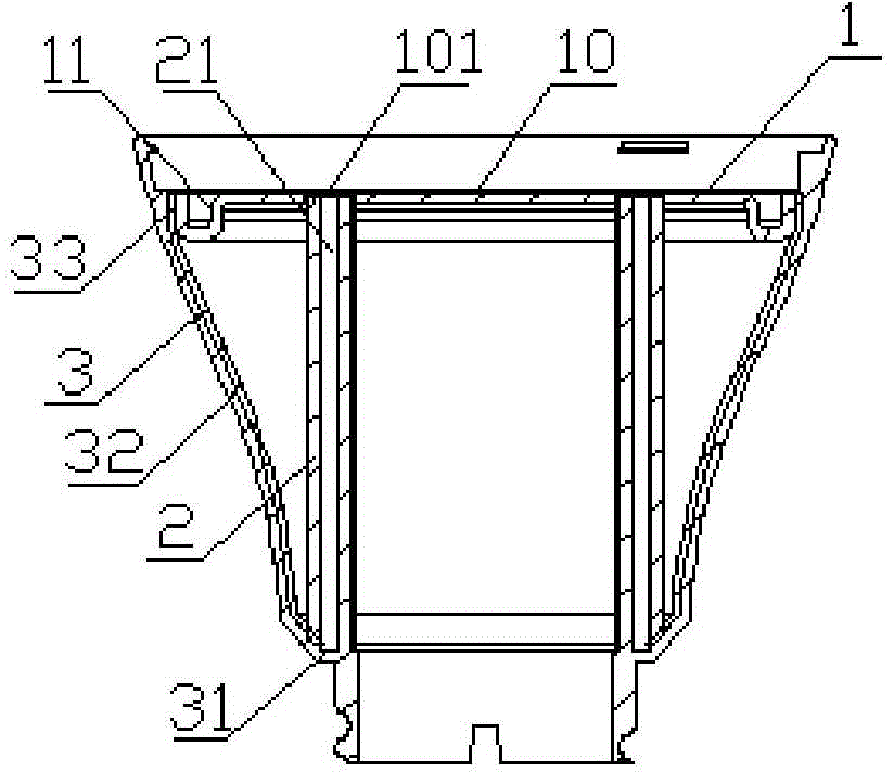
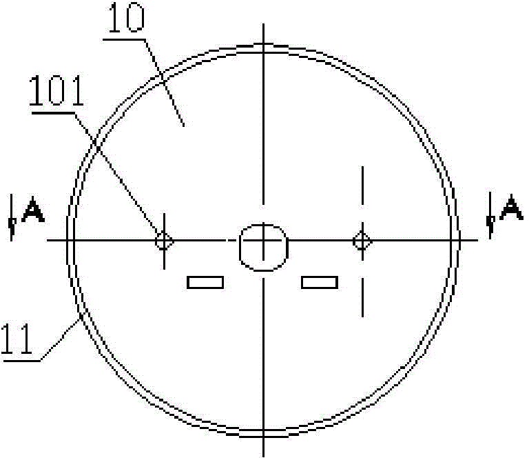
[0019] In embodiment 2, such as Figure 4 As shown, the screw hole is provided with an inversion 102, and the inversion protrudes upwards from the cover plate. When screwing the aluminum base plate before the improvement, there is no positioning hole, and manual alignment is required, which is time-consuming and laborious, and may cause misalignment of the holes and misalignment of the screws. It is based on the round hole type screw hole before improvement, and the hole is stretched back, forming a raised shape on the back of the radiator cover, which is convenient for increasing the number of effective threads of the thread when the aluminum substrate is subsequently assembled. Strengthen the fixing effect on the screw, and also play the role of not easy to slip teeth.

[0020] In addition, in this embodiment, the flange 11 is provided with a reinforcing structure, and the reinforcing structure is an indented structure 111 in which the chamfered part is recessed toward the ...

Embodiment 3

[0021] In embodiment 3, such as Figure 5 As shown, the inversion protrudes to the bottom of the cover plate. It stretches the hole on the basis of the round hole screw hole before improvement, so that the aluminum substrate can be directly fixed when the aluminum substrate is screwed, reducing unnecessary time for employees to align the hole, saving time and effort.

Embodiment 4

[0022] Example 4, such as Image 6 As shown, the flange is a U-shaped bending structure, which can increase the heat dissipation area of ​​the cover plate.


PUM


Abstract

The invention discloses an improved structure of a cover plate of a heat radiator for an LED lamp. The cover plate of the heat radiator comprises a cover plate body in the shape of a circular flat plate. Screw holes are arranged in the cover plate body. The edge of the cover plate body is provided with an upward flanging. The flanging is in contact with the inner wall of a heat radiator housing in a matching mode. The joint between the bottom of the flanging and the cover plate body is provided with a chamfer angle. The screw hole is provided with a flanging mouth. The flanging is provided with a reinforcing structure. The improved structure of the cover plate of the heat radiator for the LED lamp has following beneficial effects: during the process of subsequently assembling an aluminum substrate, the improved structure helps to increase the effective thread number of screws and enhances the effect of fixing screws; and additionally, matching between the cover plate and plastic cladding aluminum by contact is enhanced and smoothness of the cover plate is kept so that the cover plate is in full contact with the aluminum substrate for better heat radiation.

Description

technical field [0001] The invention relates to an LED lamp, in particular to an improved structure of a radiator cover plate of an LED lamp. Background technique [0002] As the cost of LED radiators continues to decrease and assembly requirements continue to increase, the requirements for radiator cover plates continue to increase. The cover plate before improvement has a phenomenon of bulging in the middle of the cover plate during assembly, resulting in a decrease in the contact area between the aluminum substrate and the cover plate. It is small and cannot dissipate heat well; the round hole type screw hole before improvement is easy to loosen when the aluminum substrate is assembled when there is no connector inside the radiator shell. It is scrapped, which increases the follow-up cost. Contents of the invention [0003] The technical problem to be solved by the present invention is to provide an improved structure of the cover plate of the radiator of the LED lamp,...

Claims


Application Information

Patent Timeline
Patent Type & Authority Applications(China)
IPC IPC(8): F21V29/70F21V17/12F21Y101/02
CPCF21V17/12
Inventor 何文健徐建宁
Owner ZHEJIANG CHENFENG SCIENCE AND TECHNOLOGY CO LTD
Why Eureka
Try Eureka