Building Contouring Machines

A technology for building outlines and forming machines, which is applied in construction, building structure, processing of building materials, etc., can solve the problems of difficult manufacturing, twisting and shaking of mechanical structures, low forming accuracy, etc., and achieves a simple and reasonable overall structure. Overcomes wiggle and wobble, easy to fabricate and deploy

Active Publication Date: 2017-05-31
博彭科技(杭州)有限公司
View PDF6 Cites 0 Cited by
  • Summary
  • Abstract
  • Description
  • Claims
  • Application Information

AI Technical Summary

Problems solved by technology

Apparently, US7814937 B2 U.S. patent, because it has adopted gantry structure, therefore can't be used for the forming of long-span and multi-storey building
Another example is the US20050196484 A1 Figure 21 A and Figure 21 In the prior art disclosed by B, it adopts the structure of skyscrapers, which can meet the molding requirements of tall buildings, but its skyscrapers cannot be moved, and the mechanical framework of its three-dimensional motion control system must be based on multiple grounded skyscrapers. , so the layout of the mechanical frame is very difficult, requires a long construction period, and the production cost is high, which limits the popularization and application of this technology
Another example is the US20050196484 A1 Figure 19 In the disclosed prior art, due to structural defects in the longitudinal (hereinafter referred to as Y-direction) guide rail system and the vertical (hereinafter referred to as Z-direction) guide rail system, the stroke of the Z-direction guide rail system is limited and cannot meet the needs of multi-storey buildings. Forming requirements, if the stroke of the Z guide rail system is increased to meet the forming requirements of multi-storey buildings, there will be twisting and shaking of the mechanical structure, resulting in low forming accuracy and serious irregularities in the formed contour rule issue
The usual means of solving twisting and shaking that are easy to think of is to enhance the rigidity of the mechanical components and improve the guiding accuracy of the guide rail system. However, this technical method must greatly increase the weight of the mechanical frame and the load of the guide rail system. The heavy mechanical frame will This brings about a sharp increase in the cost of the mechanical frame itself, the layout of the mechanical frame, and the foundation of the mechanical frame. In addition, this conventional technical method will also bring other problems, such as the need to use a small fit gap to improve the guiding accuracy of the guide rail system. Means, it may affect the movement flexibility of the moving parts, and this flexibility problem will also cause serious irregularities in the formed contour
Therefore, adopting the existing means of enhancing the rigidity of mechanical components and improving the guiding precision of the guide rail system is not only difficult to manufacture and high in production cost, but also has obvious practicability for solving the twisting and shaking of the mechanical frame of the building contour forming machine question

Method used


Image

  • Building Contouring Machines
  • Building Contouring Machines
  • Building Contouring Machines

Examples


Embodiment approach

[0071] Figures 16 to 21 It shows a preferred embodiment of the second anti-rotation structure of the Z-direction guide rail pair ZG in the sliding fit mode: the second anti-rotation structure includes two groups arranged on the Z-direction moving guide rail 32 along the Z direction Sliding groove groups, each group of sliding groove groups includes two symmetrically arranged sliding grooves 322; a detent distance Lzz extending along the Z direction is provided between the two groups of sliding groove groups; two sliding grooves 322 of the same group of sliding groove groups slide A detent distance Lzx extending along the X direction is provided between the slots 322 . Figure 22 It shows another preferred embodiment of the second anti-rotation structure of the Z-guiding rail pair ZG in the rolling fit mode: the second anti-rotation structure includes two moving guide rails 32 along the Z direction. A set of scroll wheels, each set of scroll wheels includes two sets of symmet...


PUM


Abstract

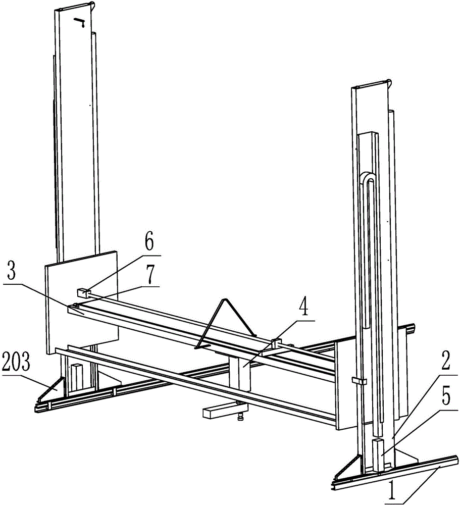
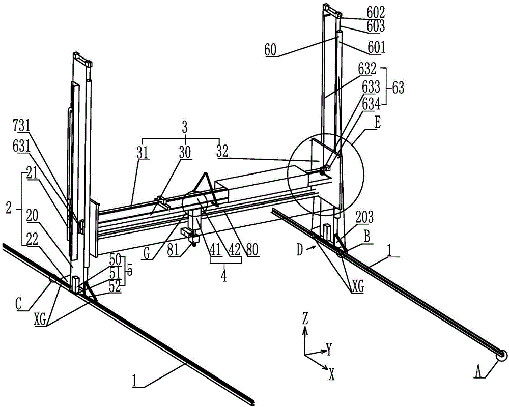
A building outline forming machine comprises basic supporting parts, X-direction moving parts, Z-direction moving parts, Y-direction moving parts, a transmission system and a material conveying system. The transmission system comprises X-direction driving parts, Z-direction driving parts and Y-direction driving parts; the X-direction driving parts can drive the X-direction moving parts to move on the basic supporting parts along an X-direction straight line; the Z-direction driving parts can drive the Z-direction moving parts to move on the X-direction moving parts along a Z-direction straight line; the Y-direction driving parts can drive the Y-direction moving parts to move on the Y-direction moving parts along a Y-direction straight line; the basic supporting parts comprise two sets of supporting pieces which are parallel to each other and two X-direction guiding rails which are arranged on the supporting pieces respectively; the X-direction moving parts comprise two stand columns, each stand column is provided with an X-direction moving rail, and the X-direction moving rails and the X-direction guiding rails slide in a matched mode. The building outline forming machine is simple and reasonable in overall structure, high in practicability, stable and low in cost.

Description

technical field [0001] The invention relates to the field of building equipment, in particular to equipment for forming building outlines, in particular to a machine capable of rapidly forming building outlines. Background technique [0002] As we all know, the existing building contours are usually formed by block stacking or concrete pouring, which has the disadvantages of long construction period, high construction cost, low degree of automation, large consumption of human and material resources, and poor environmental protection performance. U.S. Patent US7814937 B2 discloses a machine with different characteristics that can be deployed. Based on the principle of 3D printing, a nozzle for pouring concrete is controlled to move in 3D through a 3D motion control system, so as to realize the rapid prototyping of the outline of the building. Such as floors, walls, roofs, etc. This technology is still in the experimental stage. To enter the actual production, many technical ...

Claims


Application Information

Patent Timeline
Patent Type & Authority Patents(China)
IPC IPC(8): E04G21/04
Inventor B.克斯尼维斯张靖
Owner 博彭科技(杭州)有限公司
Why Eureka
Try Eureka