Locking mechanism and electric equipment using the same
A locking mechanism and locking technology, applied in the direction of electric power devices, power devices, transportation and packaging, etc., can solve problems such as time-consuming, difficult manufacturing, complex structure, etc.
- Summary
- Abstract
- Description
- Claims
- Application Information
AI Technical Summary
Problems solved by technology
Method used
Image

Examples
Embodiment 1
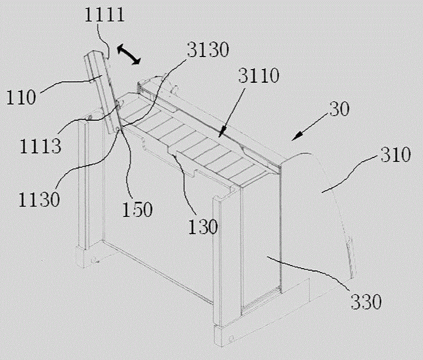
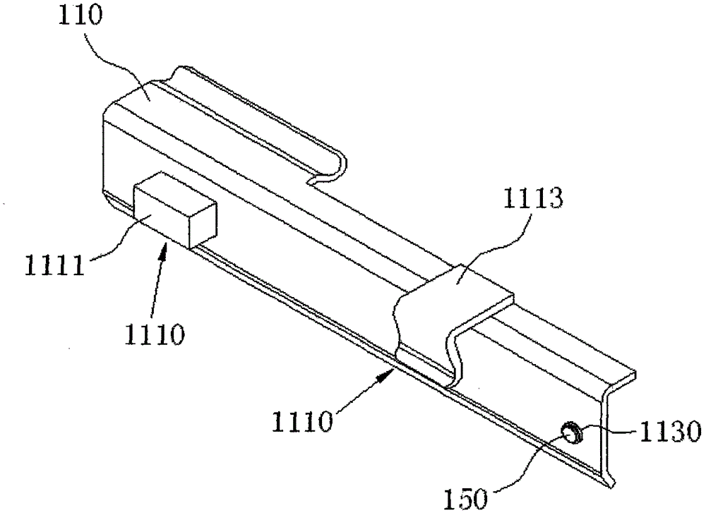
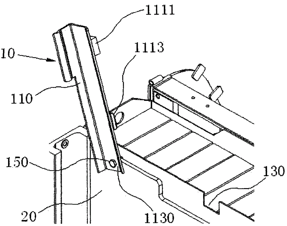
[0040] Embodiment 1, combining image 3 , Figure 4 , Figure 5 , the fixing module 1110 is fixed on the locking rod 110 through a fixed connection. The fixing module 1110 is provided with a protruding structure 1115 and a spring 1117 , and the two ends of the spring 1117 are respectively fixedly connected with the protruding structure 1115 and the locking pull rod 110 . The user presses the protruding structure 1115 to compress the spring 1117, thereby compressing the fixing module 1110. When the user releases the protruding structure 1115, the spring 1117 resets the protruding structure 1115 by virtue of its elasticity.
[0041] The connecting end 1130 is a through hole. The connection fitting 150 passes through the connection end 1130 and is fixed to a part of the device 20 to which this locking mechanism 10 is applied. The connecting end 1130 and the connecting fitting 150 can be relatively movable. The locking rod 110 in this embodiment forms a hinged connection with...
Embodiment 2
[0047] Example 2, combined with Image 6 , Figure 7 , Figure 8 , the fixing module 1110 is arranged on the locking rod 110 through a flexible connection. The fixing module 1110 is a slidable structure on the locking rod 110 , and the fixing module 1110 can slide along the axial direction of the locking rod 110 .
[0048] The limiting opening 130 is disposed on a part of the surface of the device 20 , forming a notch 1310 , and a notch 1330 is formed on one side of the notch 1310 .
[0049] When the locking mechanism 10 is about to be closed, the locking rod 110 rotates around the connecting fitting 150 until the fixed module 1110 contacts and engages with the notch 1310 of the limit opening 130; then, slide the fixed module 1110 to make the fixed module 1110 Sliding to the notch 1330 of the limiting opening 130 , and engaging with the notch 1330 .
[0050] So far, the fixing module 1110 is restricted by the notch 1330 , and the relative movement between the locking rod 1...
Embodiment 3
[0053] Example 3, combined with Figure 9 , Figure 10 , the connecting end 1130 is a slot, the connecting fitting 150 is fixed on the device 20 through the connecting end 1130 , and the connecting fitting 150 is limited in the slot of the connecting end 1130 . That is, there is a sliding connection between the connecting fitting 150 and the connecting end 1130 .
[0054] The fixing module 1110 is fixed on the locking pull rod 110 through a fixed connection. The structure of the limiting port 130 is the same as that in Embodiment 2.
[0055] When the locking mechanism 10 is about to be closed, the locking rod 110 rotates around the connecting fitting 150 until the fixed module 1110 contacts and engages with the notch 1310 of the limit opening 130; then, slides the connecting end 1130 to drive the locking rod 110 makes the fixing module 1110 slide to the notch 1330 of the limiting opening 130 , and contacts and engages with the notch 1330 .
[0056] So far, the fixing modul...
PUM
 Abstract
Description
Claims
Application Information
 - Generate Ideas
- Intellectual Property
- Life Sciences
- Materials
- Tech Scout
- Unparalleled Data Quality
- Higher Quality Content
- 60% Fewer Hallucinations
Browse by: Latest US Patents, China's latest patents, Technical Efficacy Thesaurus, Application Domain, Technology Topic, Popular Technical Reports.
© 2025 PatSnap. All rights reserved.Legal|Privacy policy|Modern Slavery Act Transparency Statement|Sitemap|About US| Contact US: help@patsnap.com