Portable electronic terminal retaining tool
一种电子终端、保持器具的技术,应用在仪器、电气元件、家里用具等方向,能够解决无法扩大拇指动作范围等问题,达到提高输入操作性、方法可靠的效果
- Summary
- Abstract
- Description
- Claims
- Application Information
AI Technical Summary
Problems solved by technology
Method used
Image
Examples
Embodiment 1
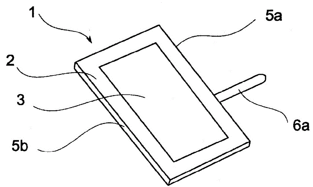
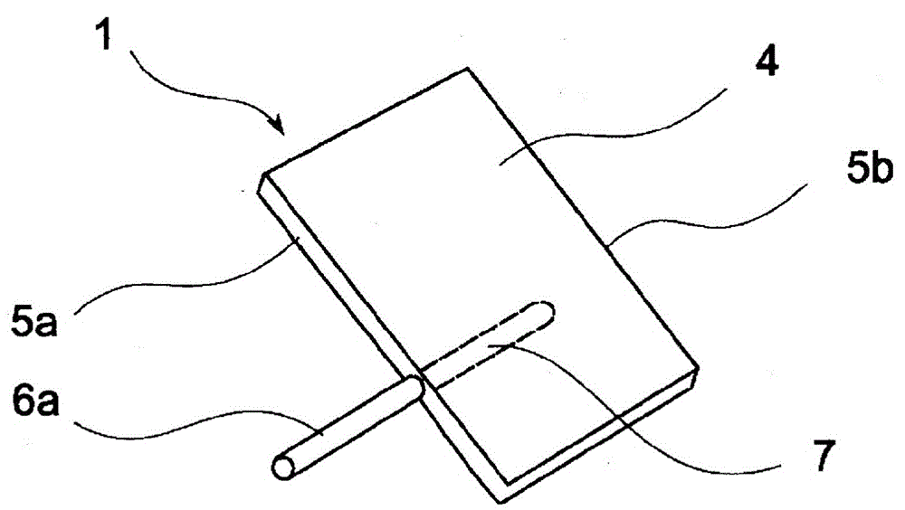
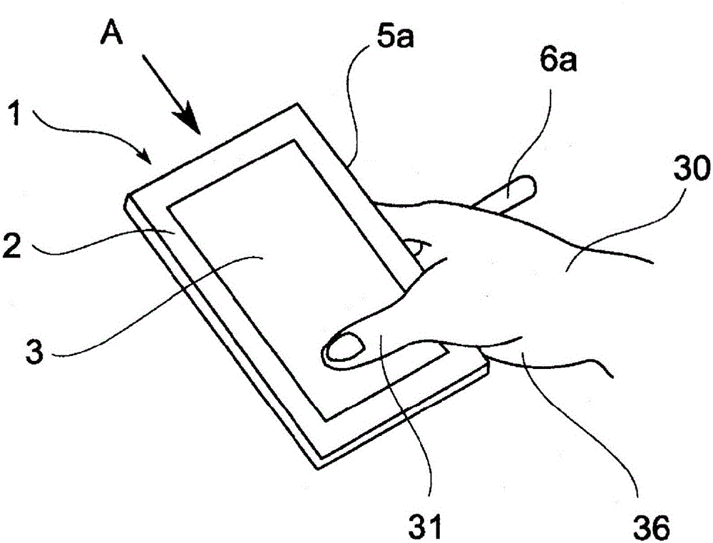
[0076] Reference Figure 1 ~ Figure 5 The structure of the portable electronic terminal holder of the first embodiment will be described. figure 1 It is a perspective view of the surface of the first embodiment of the portable electronic terminal holder of the present invention. figure 2 It is a perspective view of the back surface of the first embodiment of the portable electronic terminal holder of the present invention. image 3 It is a perspective view of the surface of the first embodiment of the portable electronic terminal holder of the present invention during use. Figure 4 It is a perspective view of the back surface of the first embodiment of the portable electronic terminal holder of the present invention during use. Figure 5 It is an arrow view when the first embodiment of the portable electronic terminal holder of the present invention is in use. In each drawing, a display portion 3 is provided on the surface 2 of the portable electronic terminal 1, and the entire...
Embodiment 2
[0084] Reference Image 6 The method of using the portable electronic terminal holder of the second embodiment will be described. Image 6 It is a perspective view of the back surface of the second embodiment of the portable electronic terminal holder of the present invention during use. Reference numerals and those of the first embodiment Figure 1 ~ Figure 5 the same. The finger seam sandwiching the rod 6a is not limited to the finger seam 38a of the index finger 32 and the middle finger 33 as in the first embodiment. In this embodiment, although the usage method is substantially the same as that of the first embodiment, the rod 6a is sandwiched by the finger slit 38b of the middle finger 33 and the ring finger 34 from the surface 2 side. If such a holding method is adopted, the portable electronic terminal 1 is held mainly at three points: the fingertip of the middle finger 33, the fingertip of the ring finger 34, and the finger gap 38b of the middle finger 33 and the ring f...
Embodiment 3
[0088] Reference Figure 7 ~ Figure 9 The structure of the portable electronic terminal holder of the third embodiment will be described. Figure 7 It is a perspective view of the surface of the third embodiment of the portable electronic terminal holder of the present invention. Figure 8 It is a perspective view of the back of the third embodiment of the portable electronic terminal holder of the present invention. Picture 9 It is an exploded perspective view of the clamping part of the third embodiment of the portable electronic terminal holder of the present invention. In each drawing, the parts common to the first and second embodiments are denoted by the same reference numerals. The portable electronic terminal 1 itself is the same as the first and second embodiments. The holder is composed of a clamping portion 8a, a clamping portion 8b, and a rod 6b.
[0089] In this embodiment, the stick 6b is a writing instrument with a pen tip 9 under a single body and made of plastic...
PUM
 Abstract
Description
Claims
Application Information
 - R&D Engineer
- R&D Manager
- IP Professional
- Industry Leading Data Capabilities
- Powerful AI technology
- Patent DNA Extraction
Browse by: Latest US Patents, China's latest patents, Technical Efficacy Thesaurus, Application Domain, Technology Topic, Popular Technical Reports.
© 2024 PatSnap. All rights reserved.Legal|Privacy policy|Modern Slavery Act Transparency Statement|Sitemap|About US| Contact US: help@patsnap.com


