Light Microscopy and Microscopy Methods

A technology of optical microscope and optical device, which is applied in the field of microscopy, can solve problems such as poor signal-to-noise ratio, achieve good signal-to-noise ratio, reduce sample light, and improve resolution

Active Publication Date: 2017-12-01
CARL ZEISS MICROSCOPY GMBH
View PDF9 Cites 0 Cited by
  • Summary
  • Abstract
  • Description
  • Claims
  • Application Information

AI Technical Summary

Problems solved by technology

[0022] In these known swirl-sheet microscopes, the range of optically limited resolution can only be reached with a poor signal-to-noise ratio

Method used


Image

  • Light Microscopy and Microscopy Methods
  • Light Microscopy and Microscopy Methods
  • Light Microscopy and Microscopy Methods

Examples


Embodiment Construction

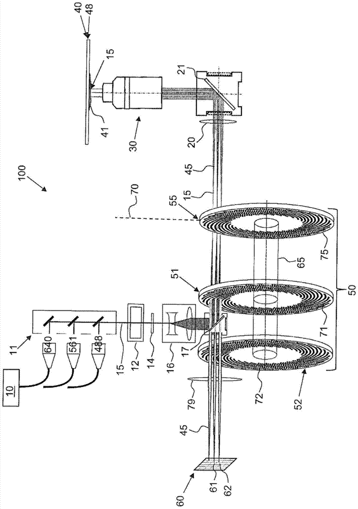
[0072] figure 2 An exemplary embodiment of an optical microscope 100 according to the invention is shown schematically. As main components, the optical microscope comprises a light source 10 for emitting illumination light 15, a sample plane 40, a detector device 60 for detecting the sample light 45, and a scanning device 50, on which the sample 41 to be investigated can be positioned. middle.

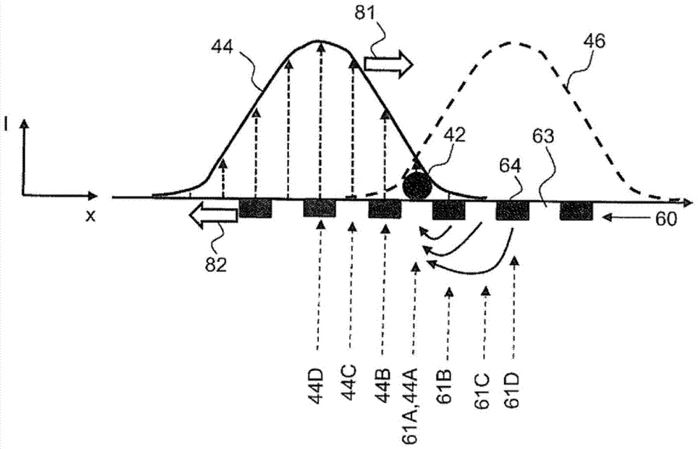
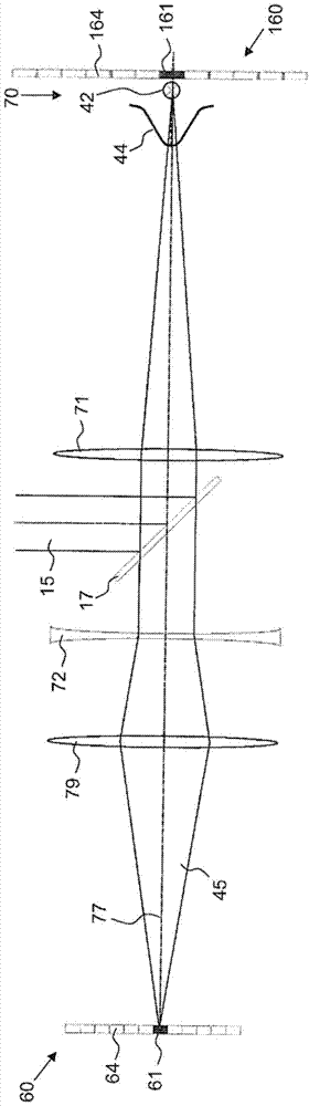
[0073] An illumination scanning movement of the illumination light beam 15 over the sample plane 40 is carried out by the scanning device 50 . Furthermore, the scanning device 50 moves the receiving region in the sample plane 40 , from which specific detector elements 61 , 62 of the detector device receive sample light. This movement is called probe scanning movement. By specially designing the scanning device 50, the directions of the illumination scanning movement and the detection scanning movement are always opposite to each other.

[0074] The light source 10 may include a pl...


PUM


Abstract

A light microscope having a sample plane for positioning a sample, and a light source for emitting illumination light, includes optical imaging means for guiding the illumination light into the sample plane. A detector device having a plurality of detector elements for detecting sample light coming from the sample. Adjacent detector elements are at a distance from one another which is smaller than an Airy-Disk produced by a point of the sample plane on the detector device. A scanning device has at least a first and a second optical arrangement simultaneously movable in a common direction for producing an illumination scanning movement and a detection scanning movement, which are opposite to one another. Sample regions spaced apart from one another can be examined simultaneously, such that both a beam path of the sample light from the sample plane to the detector device and a beam path of the illumination light from the light source to the sample plane run via the first optical arrangement and only one of these two beam paths runs via the second optical arrangement. Sample light can be imaged in a non-inverting manner and with an imaging scale of less than one. The invention is additionally directed to a corresponding microscopy method.

Description

technical field [0001] The invention relates to an optical microscope according to the preamble of claim 1 . The invention also relates to a microscopy method according to the preamble of claim 13 . Background technique [0002] An optical microscope of the type according to the invention has a sample plane on which the sample to be investigated can be positioned, a light source for emitting illumination light, an optical system for guiding the illumination light into the sample plane Imaging device and detector arrangement for detecting sample light from a sample, wherein the distance between adjacent detector elements from each other is smaller than the Airy disk produced on the detector arrangement by a point in the sample plane . Electronics determine an image of the sample based on the detected light from the sample. [0003] In a microscopy method of the type according to the invention, for the study of a sample positioned on the sample plane of an optical microscop...

Claims


Application Information

Patent Timeline
Patent Type & Authority Patents(China)
IPC IPC(8): G02B21/00G02B27/58
CPCG02B21/0032G02B21/0036G02B21/008G02B21/0044G02B21/0072G02B21/0076G02B27/58G02B21/025
Inventor W.巴思R.内茨
Owner CARL ZEISS MICROSCOPY GMBH
Why Eureka
Try Eureka