
Electrical control module heat dissipation device

A technology of electronic control module and heat dissipation device, which is applied in the direction of cooling/ventilation/heating transformation, etc. It can solve the problems that the module cannot be lowered to an appropriate temperature, the life is reduced, and the electronic component module is burned, so as to achieve good heat dissipation and cooling effect and accelerate The heat dissipation process and the effect of ensuring the heat dissipation effect

Active Publication Date: 2015-09-30
GD MIDEA HEATING & VENTILATING EQUIP CO LTD +1
View PDF6 Cites 5 Cited by
  • Summary
  • Abstract
  • Description
  • Claims
  • Application Information

AI Technical Summary

Problems solved by technology

[0002] In the heat pump air conditioning system, the electric control box, especially the outdoor machine electric control box, is the control hub of the whole system. There are a large number of electronic components and modules inside, which will generate a lot of heat. Excessive heat will accumulate in the electric control box. Make some components or modules exceed their safe operating range, make electronic components and modules work abnormally, reduce their life, and even cause electronic components or modules to burn out in severe cases. Therefore, an effective heat dissipation device is needed, which can timely and effectively Dissipate heat from the electric control box
[0003] Chinese patent CN 103648257 A discloses a heat dissipation air duct device for a frequency conversion module. The air duct structure of the entire electric control box is made into a shape suitable for heat dissipation of the frequency conversion module. The airflow generated by the fan passes through the module to achieve heat dissipation. Most of the current Manufacturers all adopt this structure, but when the module heats up seriously, it is impossible to lower the module to an appropriate temperature

Method used


Image

  • Electrical control module heat dissipation device

Examples


Embodiment Construction

[0027] The principles and features of the present invention are described below in conjunction with the accompanying drawings, and the examples given are only used to explain the present invention, and are not intended to limit the scope of the present invention.

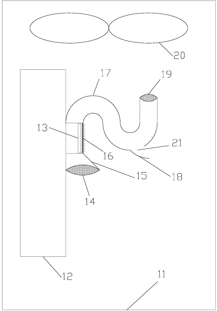
[0028] Such as figure 1 As shown, an electric control module cooling device includes an electric control box 12, an electric control module 13, a fan 20 and a radiator 16 arranged in the outdoor unit body 11, and the electric control module 13 is arranged in the electric control box 12, the fan 20 is arranged above the electric control module 13 and the radiator 16, and the radiator 16 is arranged at the end of the electric control module 13 away from the electric control box 12; The radiator 16 is provided with an air inlet and an air outlet, and the air inlet and outlet of the radiator 16 are respectively located at opposite ends of the electronic control module 13 . The installation location and installation qua...


PUM


Abstract

The invention relates to an electrical control module heat dissipation device comprising an electrical control box, an electrical control module, a fan and a radiator arranged in an outdoor unit body. The electrical control module is arranged on the outer wall of the electrical control box, the fan is arranged over the electrical control module and the radiator, and the radiator is arranged at one end, away from the electrical control box, of the electrical control module. An air inlet and an air outlet are arranged on the radiator, and the air inlet and the air outlet of the radiator are respectively located at two opposite ends of the electrical control module. Air can be led into a power module in the electrical control box in the outdoor unit body through the radiator arranged on the power module in the electrical control box, the heat dissipation process of the radiator on the power module is accelerated, and accordingly the electrical control module most serious in heat emission is cooled independently and efficiently so as to guarantee that the electrical control module can work at the most appropriate temperature.

Description

technical field [0001] The invention relates to the field of heat pump air-conditioning systems, in particular to a heat dissipation device for an electric control module. Background technique [0002] In the heat pump air conditioning system, the electric control box, especially the outdoor machine electric control box, is the control hub of the whole system. There are a large number of electronic components and modules inside, which will generate a lot of heat. Excessive heat will accumulate in the electric control box. Make some components or modules exceed their safe operating range, make electronic components and modules work abnormally, reduce their life, and even cause electronic components or modules to burn out in severe cases. Therefore, an effective heat dissipation device is needed, which can timely and effectively Dissipate and remove the heat in the electric control box. [0003] Chinese patent CN 103648257 A discloses a heat dissipation air duct device for a ...

Claims


Application Information

Patent Timeline
IPC IPC(8): H05K7/20
Inventor 舒文涛许永锋熊美兵李波杨元涛万永强钱小龙
Owner GD MIDEA HEATING & VENTILATING EQUIP CO LTD
Learn More