Upper polarizing plate for liquid crystal display and liquid crystal display

A liquid crystal display and polarizing plate technology, applied in optics, instruments, optical components, etc., can solve problems such as center contrast drop, bright spot light leakage, etc., and achieve the effect of solving bright spots and wide-area viewing angles

Inactive Publication Date: 2015-09-30
NANJING CEC PANDA LCD TECH
View PDF8 Cites 12 Cited by
  • Summary
  • Abstract
  • Description
  • Claims
  • Application Information

AI Technical Summary

Problems solved by technology

However, when the upper polarizing plate adopts a high-haze surface and the haze is 30% to 40%, its optical viewing angle will be better than that of low-haze, but its central contrast will decrease by about 20%. In addition, because the surface treatment is prone to particles of different thicknesses due to uneven coating, it will cause the problem of light leakage (mura) when pasted on the LCD panel.

Method used


Image

  • Upper polarizing plate for liquid crystal display and liquid crystal display
  • Upper polarizing plate for liquid crystal display and liquid crystal display
  • Upper polarizing plate for liquid crystal display and liquid crystal display

Examples


Embodiment Construction

[0019] Below in conjunction with accompanying drawing and specific embodiment, further illustrate the present invention, it should be understood that these embodiments are only used to illustrate the present invention and are not intended to limit the scope of the present invention, after having read the present invention, those skilled in the art understand various aspects of the present invention Modifications in equivalent forms all fall within the scope defined by the appended claims of this application.

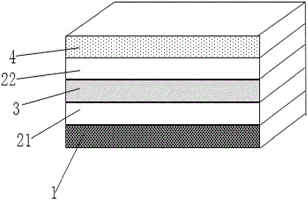
[0020] In order to overcome the problems of the prior art, the present invention provides a kind of upper polarizing plate that liquid crystal display is used, as figure 2 As shown, the polarizer includes: an adhesive layer 01 , a first protective film or optical compensation film 02 , a polarizer 03 , a second protective film 04 and a surface treatment layer 05 bonded in sequence. Wherein, the material of the polarizer 03 is a PVA (polyvinyl alcohol) film; the material...


PUM

PropertyMeasurementUnit
hazeaaaaaaaaaa
hazeaaaaaaaaaa

Abstract

The invention discloses an upper polarizing plate for a liquid crystal display. The upper polarizing plate comprises a first protective film or a light compensation film, a polarizer, a second protective film and a surface treatment layer which are sequentially attached, wherein the second protective film is a film having a concave-convex structure; the cross-section graph of the convex structure is of a trapezoid, or a circular arc or an irregular graph, wherein the size of the convex structure is of a 10 to 200micrometer grade. By means of the differentiated management of the upper polarizing plate and a lower polarizing plate of the liquid crystal display, when light passes through the second protective film of the upper polarizing plate, a part of light is scattered to AG granulate particles of the surface treatment layer of the upper polarizing plate in a squint angle direction by means of the concave-convex structure of the second protective film and are then scattered out from the AG granulate particles, so that not only is an anti-dazzling effect achieved, but also a wide-area viewing angle can be obtained, and meanwhile, the problem of bright spots of the polarizing plate is also solved.

Description

technical field [0001] The invention belongs to the field of liquid crystal display devices and relates to the structure of a polarizing plate for a liquid crystal display device. Background technique [0002] A liquid crystal display device includes a liquid crystal panel and a backlight system. The liquid crystal panel is composed of a liquid crystal layer sandwiched between two layers of glass substrates, and polarizers are pasted on the upper and lower outer surfaces of the glass substrates. Liquid crystal display devices use liquid crystals and polarizers to realize the optical switch function, liquid crystals are used to modulate polarized light, and polarizers are used to form polarized light and selectively absorb polarized light. Usually, the materials of the upper and lower polarizers attached to the upper and lower outer surfaces of the liquid crystal panel are basically the same, and each polarizer consists of a layer of polarizer PVA (polyvinyl alcohol) and a d...

Claims


Application Information

Patent Timeline
Patent Type & Authority Applications(China)
IPC IPC(8): G02B5/30G02B1/14G02B1/118G02F1/1335
CPCG02B5/30G02B1/118G02B5/0242G02F1/133528
Inventor 林佳玲
Owner NANJING CEC PANDA LCD TECH
Why Eureka
Try Eureka