Cable holding device
A cable clip and clip body technology, which is applied in the direction of cable installation, cable accessories, electrical components, etc., can solve the problems of single application, limited application, etc., and save working time.
- Summary
- Abstract
- Description
- Claims
- Application Information
AI Technical Summary
Problems solved by technology
Method used
Image
Examples
Embodiment 1
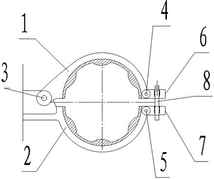
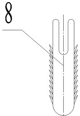
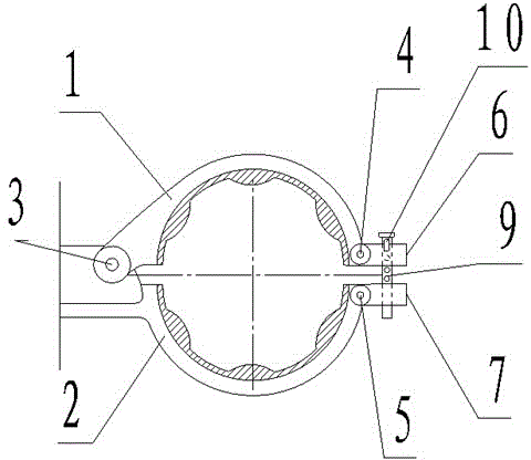
[0021] Embodiment one, as image 3 As shown, the first bayonet socket 6 and the second bayonet socket 7 are provided with corresponding through holes, and T-shaped pins 9 are installed in the through holes. The schematic diagram of T-type latch 9 is as Figure 4 As shown, the bolt 9 is provided with equidistant round holes, and the concave fixed pin 10 is inserted into the round hole of the T-shaped bolt 9 to connect and fasten the upper and lower clip bodies. The schematic diagram of the concave fixed pin 10 is as follows Figure 5 shown.
[0022] When in use, after the cable is placed in the clip body and the upper and lower clips are closed, the T-shaped pin 9 is inserted into the through hole, and the concave-shaped fixed pin 10 is inserted into the most suitable round hole of the pin 9 to engage the cover plate 1 and the fixed plate 2 , the use of T-shaped pins and concave fixed pins can quickly fasten the upper and lower clamps, saving a lot of time for tightening and ...
PUM
 Abstract
Description
Claims
Application Information
 - Generate Ideas
- Intellectual Property
- Life Sciences
- Materials
- Tech Scout
- Unparalleled Data Quality
- Higher Quality Content
- 60% Fewer Hallucinations
Browse by: Latest US Patents, China's latest patents, Technical Efficacy Thesaurus, Application Domain, Technology Topic, Popular Technical Reports.
© 2025 PatSnap. All rights reserved.Legal|Privacy policy|Modern Slavery Act Transparency Statement|Sitemap|About US| Contact US: help@patsnap.com


