
Drilling machine

A technology of drilling machine and drill bit, which is applied in the direction of boring/drilling, drilling/drilling equipment, metal processing machinery parts, etc. Work efficiency, excellent quality effect

Inactive Publication Date: 2015-09-30
XINCHANG HUAXIONG MACHINERY
View PDF0 Cites 0 Cited by
  • Summary
  • Abstract
  • Description
  • Claims
  • Application Information

AI Technical Summary

Problems solved by technology

The fixture is in a fixed position, which makes it difficult to accurately position and drill different objects to be drilled, so that this problem can only be solved by adjusting the position of the fixture. Such a production method leads to low production efficiency and high production costs.

Method used


Image

  • Drilling machine

Examples


Embodiment Construction

[0011] Below in conjunction with accompanying drawing, the present invention will be further described:

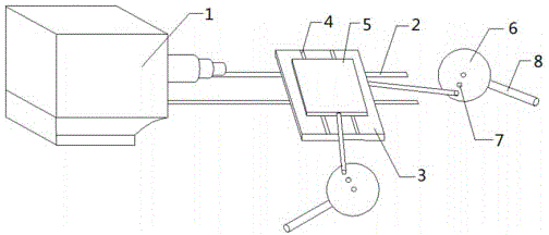
[0012] The present invention drills the object to be drilled by installing a drill bit on the driving part 1, such as figure 1 As shown, the drilling machine includes a first guide rail 2 , a first movable plate 3 , a second guide rail 4 , a second movable plate 5 and two regulating parts 6 . Both the driving part 1 and the first movable plate 3 can be movably installed on the first guide rail 2, so that the relative positions of the driving part 1 and the first movable plate 3 can be flexibly adjusted to adapt to objects of different sizes, The occurrence of reinstalling the driving part 1 and / or the first movable plate 3 due to the limitation of the distance between the driving part 1 and the first movable plate 3 is completely avoided. The second guide rail 4 is located on the upper surface of the first movable plate 3 and the length direction of the second guide rail ...


PUM


Abstract

The invention relates to a drilling machine. The drilling machine is characterized by comprising a first guide rail, a first movable plate, a second guide rail, a second movable plate and two regulating and control portions. Due to the fact that the first guide rail and the second guide rail are arranged, the position of a driving portion and the position of the first movable plate can be adjusted along the first guide rail, and the position of the first movable plate can be adjusted along the second guide rail. Therefore, the position of a drilled object on the second movable plate can be adjusted in the transverse direction and the longitudinal direction, the quality of a drilled hole is more excellent, and drilling efficiency is higher. The regulating and control portions are further arranged, the position of the first movable plate and the position of the second movable plate can be adjusted more conveniently and faster, and work efficiency is improved.

Description

technical field [0001] The invention relates to a drilling machine. Background technique [0002] Drilling machine refers to the general name of machinery and equipment that leaves cylindrical holes or holes on the object to be drilled by means of rotary cutting or rotary extrusion using a tool that is harder and sharper than the object to be drilled. In the prior art, the object to be drilled in the drilling process is placed on the jig and then the object to be drilled is drilled with a drill bit. The fixed position of the jig makes it difficult to accurately position and drill different objects to be drilled, so that this problem can only be solved by adjusting the position of the jig. Such a production method leads to low production efficiency and high production costs. Contents of the invention [0003] Aiming at the problems existing in the prior art, the object of the present invention is to provide a technical solution for a drilling machine. [0004] A kind of d...

Claims


Application Information

Patent Timeline
Patent Type & Authority Applications(China)
IPC IPC(8): B23B39/00B23Q1/25
CPCB23B39/00B23Q1/621
Inventor 俞玉华
Owner XINCHANG HUAXIONG MACHINERY
Learn More