
A new device for separating copper powder in waste liquid

A technology for separating waste liquid and separation device, applied in the direction of filtration separation, separation method, mobile filter element filter, etc., can solve the problems that waste liquid cannot continue to be discharged from the electrolytic cell, copper powder is easy to block, and environmental pollution, etc., to achieve Avoid sputtering everywhere, complete separation, and improve separation efficiency

Inactive Publication Date: 2016-10-05
CHENGDU HONGHUA ENVIRONMENTAL SCI & TECH CO LTD
View PDF5 Cites 0 Cited by
  • Summary
  • Abstract
  • Description
  • Claims
  • Application Information

AI Technical Summary

Problems solved by technology

[0002] At present, the surface of most metal parts (such as door handles, keys, etc.) must be copper plated to make the surface brighter. The copper plating on the surface is carried out in the electroplating solution. However, there is a large amount of copper powder in the waste liquid. Once it is discharged to the outside, it will not only cause environmental pollution, but also cause waste of copper powder, which is very uneconomical.
At present, most enterprises usually use filters to filter out copper powder. The operation is to install a filter at the discharge port of the electrolytic cell. When the waste liquid passes through the filter, the copper powder is intercepted in the electrolytic cell, and the waste liquid passes through the filter. The filter screen is discharged from the electrolytic tank. Although this method can effectively separate the copper powder, the copper powder is easy to block the filter screen, so that the waste liquid cannot continue to be discharged from the electrolytic tank.

Method used


Image

  • A new device for separating copper powder in waste liquid
  • A new device for separating copper powder in waste liquid
  • A new device for separating copper powder in waste liquid

Examples


Embodiment Construction

[0011] The present invention will be further described below in conjunction with accompanying drawing, protection scope of the present invention is not limited to the following:

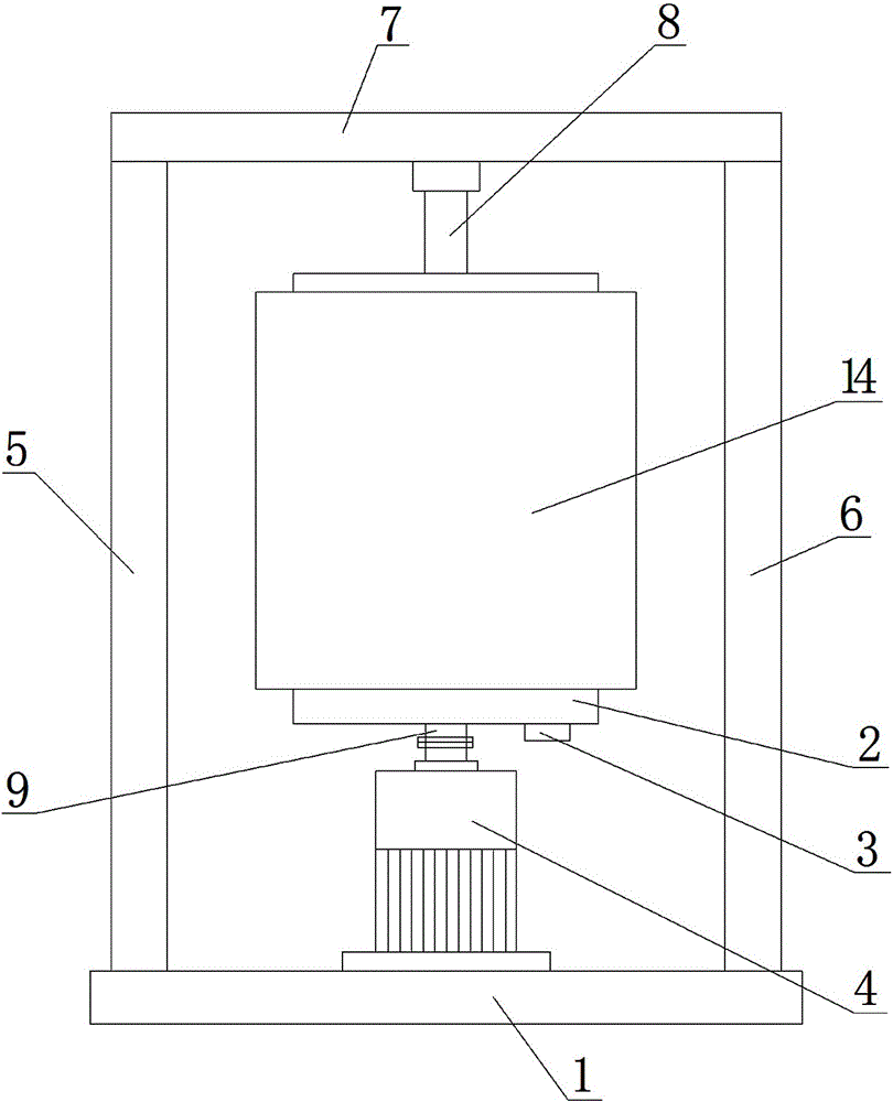
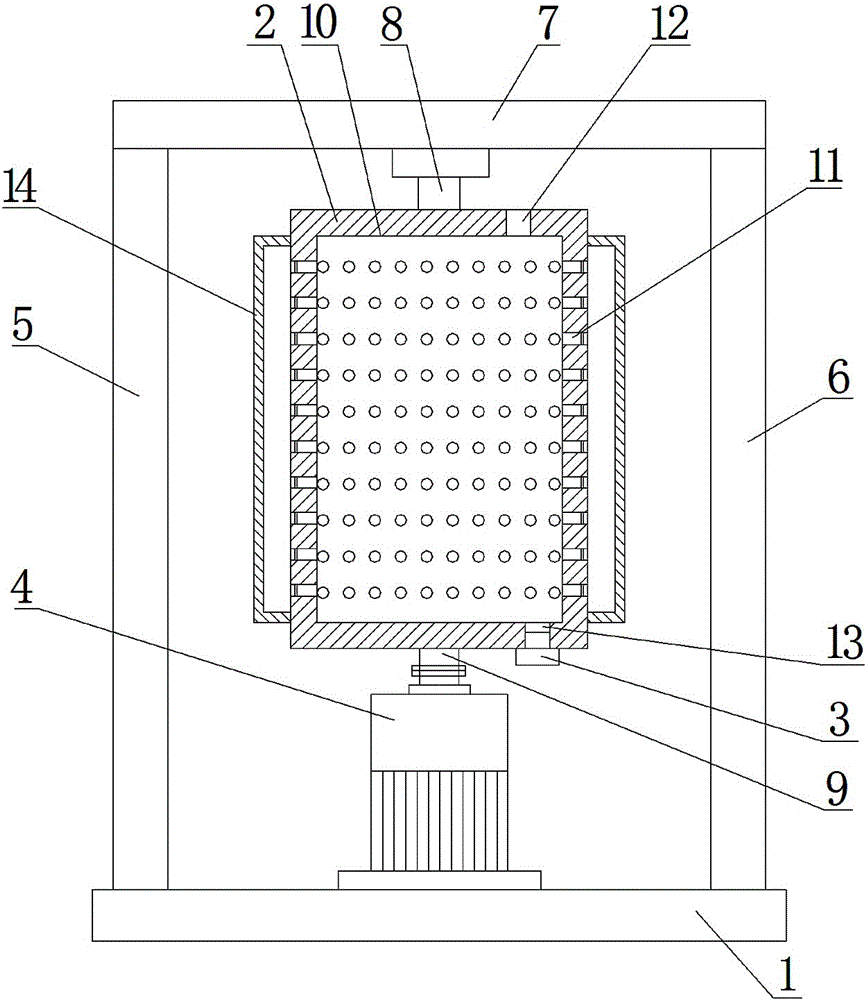
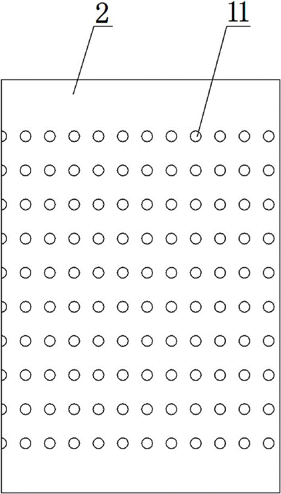
[0012] Such as Figure 1-3 As shown, a new type of device for separating copper powder in waste liquid, it includes a workbench 1, a filter cartridge 2, a motor 4, and a column A5 and a column B6 arranged on the workbench 1, the motor 4 is vertically arranged and It is fixedly installed on the workbench 1, and a beam 7 is arranged between the column A5 and the column B6. Such as Figure 1-3 As shown, the filter cartridge 2 is in a cylindrical shape, and the filter cartridge 2 is arranged between the column A5 and the column B6. The upper and lower ends of the filter cartridge 2 are respectively provided with a rotating shaft I8 and a rotating shaft II9, and the rotating shaft I8 is rotatably mounted on the beam 7 , the rotating shaft II9 is ​​connected to the output end of the motor 4, the middle p...


PUM


Abstract

The invention discloses a novel device for separating copper powder from waste liquid. The device includes a working table (1), a filter drum (2), a motor (4), as well as a stand column A (5) and a stand column B (6) which are both arranged on the working table (1), wherein a rotating shaft II (9) is connected with the output end of the motor (4); a cavity (10) is formed in the middle of the filter drum (2); a plurality of through holes (11) communicated with the cavity (10) are distributed uniformly in the cylindrical surface of the filter drum (2); a liquid inlet (12) and a discharge opening (13), which are communicated with the cavity (10), are respectively arranged formed in the upper end and the lower end of the filter drum (2); a plug (3) is arranged in the discharge opening (13); the device further includes a liquid collection bag (14) which surrounds the filter drum (2); a cavity is formed between the liquid collection bag (14) and the filter drum (2). The novel device for separating copper powder from waste liquid has the benefits that the copper powder separation is thorough, separation efficiency is high, and the operation is simple,; manual copper powder collection is facilitated and waste liquid is prevented from splashing.

Description

technical field [0001] The invention relates to a novel device for separating copper powder in waste liquid. Background technique [0002] At present, the surface of most metal parts (such as door handles, keys, etc.) must be copper plated to make the surface brighter. The copper plating on the surface is carried out in the electroplating solution. However, there is a large amount of copper powder in the waste liquid, once it is discharged to the outside, it will not only cause environmental pollution, but also cause waste of copper powder, which is very uneconomical. At present, most enterprises usually use filters to filter out copper powder. The operation is to install a filter at the discharge port of the electrolytic cell. When the waste liquid passes through the filter, the copper powder is intercepted in the electrolytic cell, and the waste liquid passes through the filter. The filter screen is discharged from the electrolytic tank. Although this method can effective...

Claims


Application Information

Patent Timeline
Patent Type & Authority Patents(China)
IPC IPC(8): B01D33/067B01D33/11
Inventor 韦建敏赵兴文张晓蓓张小波
Owner CHENGDU HONGHUA ENVIRONMENTAL SCI & TECH CO LTD
Learn More