An optimized mechanical filter

A technology of mechanical filter and liquid separator, which is applied in the direction of gravity filter, loose filter material filter, filtration separation, etc. Avoid problems such as bias flow, so as to avoid the phenomenon of liquid collector breaking or buckle loosening and bias flow, improve the filtration flux, and prevent the effect of bias flow

Active Publication Date: 2017-07-04
浙江安耐杰科技股份有限公司
View PDF4 Cites 0 Cited by
  • Summary
  • Abstract
  • Description
  • Claims
  • Application Information

AI Technical Summary

Problems solved by technology

The existing mechanical filter includes a mechanical filter cylinder, the top of the mechanical filter cylinder is provided with an inlet, the inlet is provided with a liquid separator, the lower part of the mechanical filter cylinder is provided with an outlet, and the outlet is provided with a liquid collector. The liquid container is provided with a porous plate and a filter cap, and the porous plate is provided with fillers. The liquid separator and the liquid collector are respectively fixed by the support assembly 1 and the support assembly 2. The support assembly 1 and the support assembly 2 adopt a steel frame structure or Combined grille, the mechanical filter of this structure has the following defects: First, since the porous plate of the liquid collector is provided with fillers, the fillers are easy to enter into the water filter cap of the liquid collector, thereby easily blocking the filter. The gap in the water cap reduces the filtration flux; second, because the liquid collector cannot achieve complete symmetry, the liquid collector is prone to bias flow; third, the liquid separator and the liquid collector are respectively supported by the support component 1 and the The second component is fixed, and the supporting component 1 and the supporting component 2 adopt steel frame structure or combined grid plate. When the supporting component 1 and the supporting component 2 are combined grid plates, the grid plate is easy to break or buckle loose.

Method used


Image

  • An optimized mechanical filter

Examples


Embodiment Construction

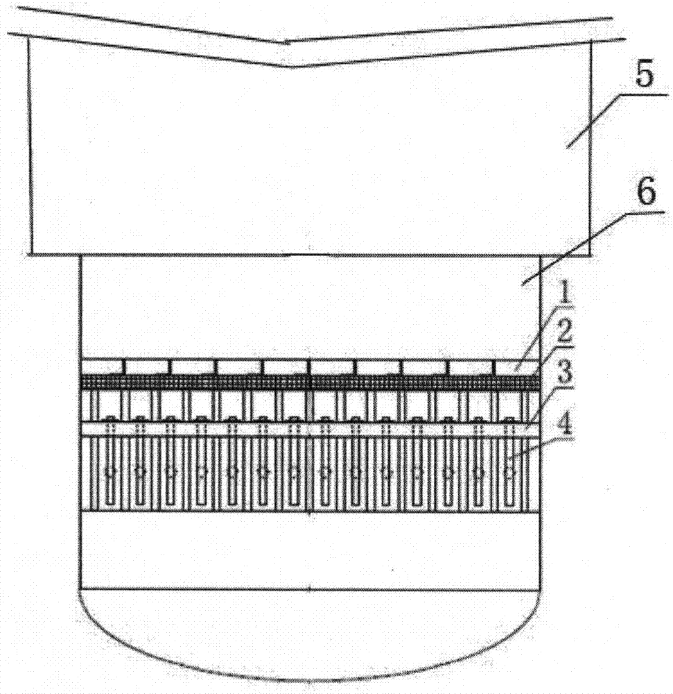
[0015] Such as figure 1 As shown, an optimized mechanical filter includes a cylinder body 5, the upper part of the cylinder body 5 is provided with an inlet, the inlet is provided with a liquid separator, the liquid separator is fixed by a support assembly, the lower part of the cylinder body 5 is provided with an outlet, and the outlet is provided with There is a liquid collector 6, a porous plate 3 is arranged in the liquid collector 6, a filler is arranged on the porous plate 3, several identical water pipes 4 are connected at the outlet, and water pipe holes having the same size as the water pipe 4 are arranged on the porous plate 3, several Two identical water pipes 4 pass through the corresponding water pipe holes on the perforated plate 3, so that the liquid confluence is more relaxed and no strong turbulent disturbance is generated. A water pipe hole stand plate 1 is arranged on the circumference of the upper surface of each water pipe hole, and the water pipes Hole ri...


PUM


Abstract

The invention discloses an optimized mechanical filter which comprises a cylinder. An inlet is formed in the upper portion of the cylinder, a liquid dispenser is arranged at the position of the inlet and is fixed through a supporting module, an outlet is formed in the lower portion of the cylinder, a liquid collector is arranged at the position of the outlet, a perforated plate is arranged in the liquid collector, a filler is arranged on the perforated plate, a plurality of same water pipes are connected to the position of the outlet, the perforated plate is provided with water pipe holes equal to the water pipes in size, water pipe hole vertical plates I are arranged on the circumferences of the upper surfaces of the water pipe holes, a plurality of rib plates I are connected to the water pipe hole vertical plates I, water pipe hole vertical plates II are arranged on the circumferences of the lower surfaces of the water pipe holes, a plurality of rib plates II are connected to the water pipe hole vertical plates II, air holes are formed in each rib plate II, a grid plate assembly is arranged on the upper surface of the perforated plate and is covered with a steel angle welding support, and the supporting module is of a steel angle welding frame structure. The optimized mechanical filter is reasonable in design, the filtered water flux can be well increased, and liquid collector breakage or fastener loosening and bias flow phenomena are also avoided.

Description

technical field [0001] The invention relates to the technical field of purification filters, in particular to an optimized mechanical filter. Background technique [0002] Mechanical filter is also called pressure filter. It is an important part of the pretreatment and water purification system of pure water preparation. The existing mechanical filter includes a mechanical filter cylinder, the top of the mechanical filter cylinder is provided with an inlet, the inlet is provided with a liquid separator, the lower part of the mechanical filter cylinder is provided with an outlet, and the outlet is provided with a liquid collector. The liquid container is provided with a porous plate and a filter cap, and the porous plate is provided with fillers. The liquid separator and the liquid collector are respectively fixed by the support assembly 1 and the support assembly 2. The support assembly 1 and the support assembly 2 adopt a steel frame structure or Combined grille, the mecha...

Claims


Application Information

Patent Timeline
Patent Type & Authority Patents(China)
IPC IPC(8): B01D24/14B01D24/40
Inventor 史俊石瑞清郎立萌刘晶晶边展毅杨宝良
Owner 浙江安耐杰科技股份有限公司
Why Eureka
Try Eureka