Dynamic current sharing control method and circuit

A flow control and dynamic technology, applied in the direction of electrical components, output power conversion devices, etc., can solve the problems of undervoltage, reduced circuit reliability, affecting the dynamic response of the system, etc., to achieve simple circuit structure, reduced load current, and application range wide effect

Active Publication Date: 2015-09-23
O&C ELECTRIC TECHN CO LTD
View PDF5 Cites 8 Cited by
  • Summary
  • Abstract
  • Description
  • Claims
  • Application Information

AI Technical Summary

Problems solved by technology

However, since each power module uses "maximum current" as the base value of output current, except for the power module whose actual output current is the maximum value, the output current of other power modules must be adjusted upwards, and only the power module whose output current is the maximum value The output current of the module will drop. Under the condition of constant load, the increase of the output current of multiple power modules must be greater than the decrease of the output current of a single power module. As a result, the output voltage of the power module is higher than the rated voltage, resulting in "Overvoltage"; or "minimum current" as the base value of the output current, resulting in "undervoltage"; both of these will adversely affect the reliability and safety of the power supply and load, and affect the dynamic response of the entire system
[0004] In addition, due to the fact that any combination of multiple power modules and random parallel connection will cause current imbalance among the outputs, and the implementation is more complicated, the corresponding cost and circuit volume will increase accordingly, and the overall circuit The reliability is reduced, so most of the existing current sharing control circuits use a single output, and the application range is narrow

Method used


Image

  • Dynamic current sharing control method and circuit
  • Dynamic current sharing control method and circuit

Examples


Embodiment 1

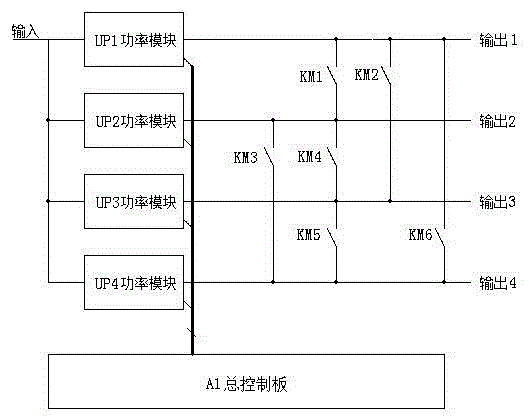
[0038] This embodiment is described by taking the rail transit vehicle-mounted inverter as an example. like figure 1Shown: The auxiliary power supply cabinet of the locomotive includes four groups of power modules UP1~UP4 working in parallel, the main control board A1, the control switches KM1~KM6, and each power module has its own sub-control board; among them, the main control board A1 is used for Collect the load current signals of power modules UP1~UP4 for quick calculation, and re-issue the load current distribution command of power modules UP1~UP4 to adjust the current limiting value of power modules UP1~UP4; the sub-control board is used to control the respective power modules UP1~UP4 The current; the control switches KM1~KM6 are used to control any dynamic combination between the power modules UP1~UP4, and random parallel connection. The connection relationship of all the above devices is as follows: the power modules UP1~UP4 are connected in parallel, the control swi...

Embodiment 2

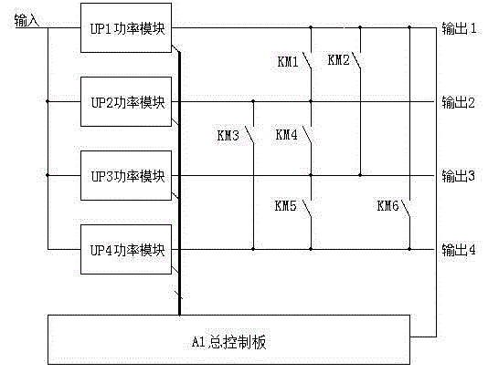
[0048] This embodiment is described by taking the rail transit vehicle-mounted inverter as an example. like figure 2 Shown: The auxiliary power supply cabinet of the locomotive includes four groups of power modules UP1~UP4 working in parallel, the main control board A1, the control switches KM1~KM6, and each power module has its own sub-control board; among them, the main control board A1 is used for Collect the load current signals of the power modules UP1~UP4 for quick calculation and re-issue the load current distribution instructions of the power modules UP1~UP4 to adjust the current limiting value of the power modules UP1~UP4; the main control board A1 is also used to obtain the power modules UP1~UP4 The total output current on the mains. The sub-control board is used to control the current of the respective power modules UP1, UP2, UP3, UP4; the control switches KM1~KM6 are used to control any dynamic combination between the power modules UP1~UP4, and random parallel co...


PUM


Abstract

The invention relates to a dynamic current sharing control method and circuit. A control circuit comprises a plurality of power modules connected in series, a main control panel, sub control panels and control switches, wherein the sub control panels and the control switches are in same numbers of the power modules, dynamic current sharing reference data is transmitted between the main control panel and the sub control panel of each power module through communication, through each control switch at an output end, multiple output is achieved by each power module, and dynamic current sharing control after arbitrary numbers of the power modules are connected in series is achieved. The invention also comprises another control method and two control circuits. By adopting the control method and circuit disclosed by the invention, a current sharing state can be reached after the plurality of power modules are arbitrarily combined and randomly connected in series, and the reliability of current sharing is further guaranteed.

Description

technical field [0001] The invention relates to the technical field of power electronics, in particular to a dynamic current sharing control method and circuit. Background technique [0002] When the power modules designed with semiconductor components are used in parallel, the load of the parallel-operated power modules cannot be balanced due to factors such as differences in the characteristics of semiconductor components, differences in external circuits, and load disturbances. The modules are evenly distributed, and in severe cases, the power modules are even burned, which has become a major technical barrier in engineering applications. [0003] There are many traditional solutions, such as increasing the design margin of the power module to ensure normal operation even in the case of uneven current sharing. However, the price of this solution is that in order to increase the design margin, it is necessary to select components with more than double the power, thereby m...

Claims


Application Information

Patent Timeline
Patent Type & Authority Applications(China)
IPC IPC(8): H02M1/32
Inventor 黄柱舒均庆王颖曜杨斌刘凡姚远蒙火成黄翔
Owner O&C ELECTRIC TECHN CO LTD
Why Eureka
Try Eureka