
Method for determining wheel-track type reflector antenna pointing error

A technology for antenna pointing and determining methods, which is applied in the directions of measurement devices, instruments, surveying and navigation, etc., and can solve problems such as non-generality, other antenna designs not instructive, and no consideration of orbital unevenness.

Inactive Publication Date: 2015-09-23
XIDIAN UNIV
View PDF4 Cites 18 Cited by
  • Summary
  • Abstract
  • Description
  • Claims
  • Application Information

AI Technical Summary

Problems solved by technology

Through the study of the above method, the disadvantages are summarized as follows: (1) Most of the literature considers the method based on experimental measurement to analyze the influence of shafting error on pointing error after the antenna is built. This method is only applicable to a specific antenna , is not general, and has no guiding significance for the design of other antennas; (2) Although some literatures have established the influence relationship between the shafting error and the pointing error, they have not considered the influence of the track irregularity
[0005] To sum up, there is currently no analysis method that considers the orbit error of the antenna and the comprehensive axis system errors such as the azimuth axis, pitch axis, and mechanical axis to study its impact on the antenna pointing error.

Method used


Image

  • Method for determining wheel-track type reflector antenna pointing error
  • Method for determining wheel-track type reflector antenna pointing error
  • Method for determining wheel-track type reflector antenna pointing error

Examples


Embodiment Construction

[0064] The present invention will be further described below in conjunction with the accompanying drawings. It should be noted that this embodiment is based on the technical solution, and provides detailed implementation and specific operation process, but the protection scope of the present invention is not limited to the present invention. Example.

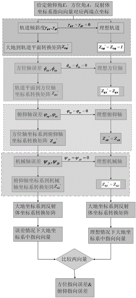
[0065] Such as figure 1 As shown, the method for determining the pointing error of the wheel-rail reflector antenna includes the following steps:

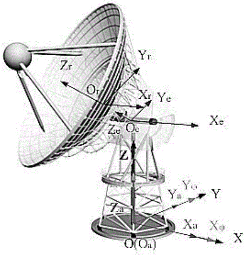
[0066] S1 For the wheel-rail reflector antenna, the radius of the azimuth track is r, the height of the azimuth mount is h, and the distance between the center point of the pitch axis and the apex of the reflector is h 1 , when the azimuth and elevation angles of the antenna are A and E respectively, calculate from the earth coordinate system OXYZ to the reflector coordinate system O r x r Y r Z r The transformation matrix of Z is L :

[0067] Z L = Z EJ ·Z AE ·Z φA ·Z Oφ...


PUM


Abstract

The invention discloses a method for determining a wheel-track type reflector antenna pointing error. The problems that an existing analysis method cannot give complete consideration to factors of out-of-level tracks, non-plumb azimuth axes, non-vertical pitch axes, non-vertical pitch azimuth axes and non-vertical mechanical axes and pitch axes, and the relationship between a comprehensive axial system error and the antenna pointing error cannot be built are solved. The method includes the implementation steps that according to wheel-track type reflector antenna model parameters, a conversion matrix of a geodetic coordinate system to a reflector coordinate system under the ideal condition, namely the axial-system-error-free condition is built, and the pointing vector quantity under the ideal condition is obtained; then according to the axial system error distribution condition, a conversion matrix under the condition that the error exists is built, and the pointing vector quantity at the time is obtained; the azimuth and pitching pointing errors are accordingly obtained. According to the method, the influences of the comprehensive axial system error on the antenna pointing error are systematically considered, a foundation is laid to designing a follow-up high-pointing-accuracy antenna, and the development period is shortened.

Description

technical field [0001] The invention belongs to the technical field of antennas, in particular to a method for determining the pointing error of a wheel-rail reflector antenna, which is used to guide the design of a large-scale wheel-rail reflector antenna. Background technique [0002] In order to detect more and weaker celestial bodies, reflector antennas are required to have higher angular resolution and sensitivity, which makes antennas develop in the direction of high-frequency bands and large apertures. Many radio telescope antennas with apertures up to 100 meters have been established at home and abroad. Pointing accuracy is an extremely important performance index of a radio telescope, reflecting the ability of the antenna system to accurately point to the target azimuth. Its level not only affects the throughput of the telescope communication system, the system accuracy of laser ranging, and the operational efficiency of the tracking system, but also affects its ab...

Claims


Application Information

Patent Timeline
IPC IPC(8): G01C1/00
CPCG01C1/00
Inventor 李素兰李娜米建伟朱韵茹冯树飞保宏王从思吴江班友项斌斌
Owner XIDIAN UNIV
Learn More